Shrinkage Porosity in Die Casting -Causes, Locations...
Shrinkage porosity in die casting: why it forms in thick sections, how it differs from gas porosity, how to identify it on X-ray...
Supporting Visuals
Defect reference visuals for shrinkage porosity die casting
These images are pulled from your current KastMfg asset library. Page-specific files automatically override shared fallback visuals when you add them later.
Defect Example Image
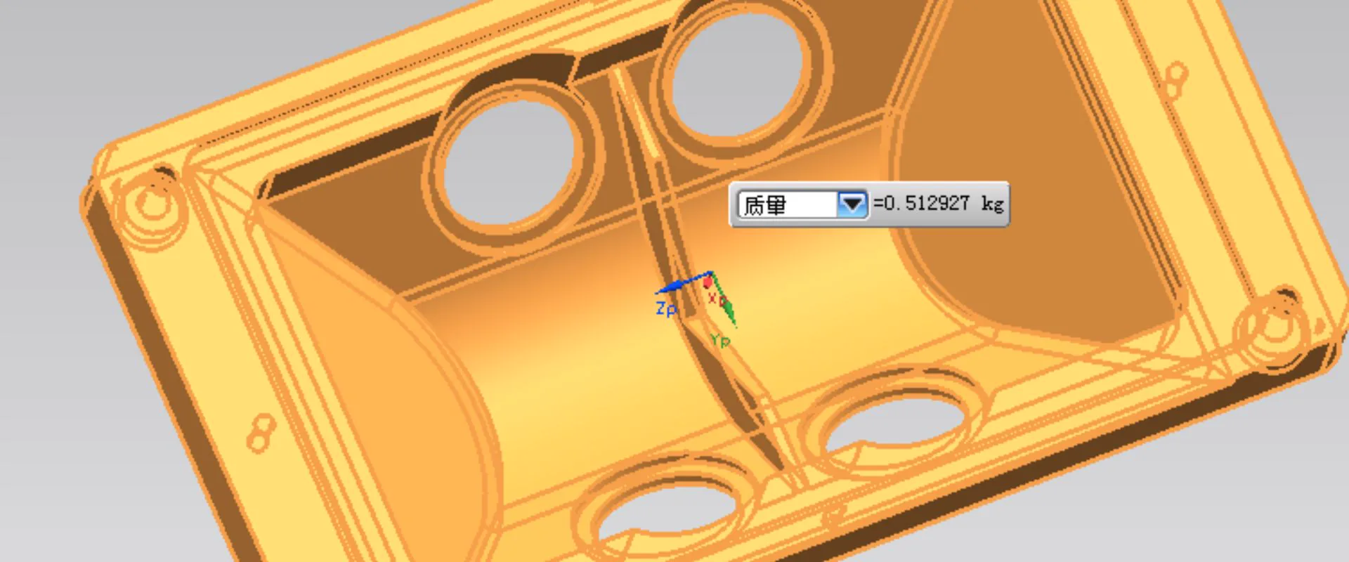
Reserve one clear defect photo, X-ray, CT scan, or sectioned sample that visually identifies the defect being discussed.
Best as a technical reference image
Corrective Action Image
Use a second image for tooling changes, gating adjustments, leak testing, or inspection steps that show how the defect is controlled.
Best as a process-improvement photo
Shrinkage porosity is the second most common internal defect in aluminum die casting, after gas porosity -and unlike gas porosity, it is almost entirely a design and tooling problem rather than a process problem. Understanding why it forms leads directly to the design changes that prevent it.
What Shrinkage Porosity Is
Shrinkage porosity consists of irregular, branching voids concentrated in the thickest sections of the casting. Under X-ray, they appear as angular, dendritic dark regions -distinctly different from the round, smooth-walled voids of gas porosity. Under metallographic cross-section, the walls show dendritic structure with angular, branching character.
Why It Forms in Thick Sections
Aluminum contracts approximately 3.5-% by volume during solidification. For this shrinkage to produce a sound casting, liquid metal must continuously feed the solidifying region until fully solid.
In thin sections: the entire wall solidifies quickly and simultaneously. Shrinkage is small and distributed -not a significant defect.
In thick sections: the outside surfaces solidify first (contacted by the cooler die), while the interior remains liquid. As the interior eventually solidifies and contracts, there is insufficient liquid metal available to feed it -because the solidified shell has already sealed off the feed path. The result: a void in the interior of the thick section.
Where Shrinkage Porosity Appears -Predictable Locations
- Isolated thick sections: Bosses, ribs, and pads significantly thicker than the surrounding wall
- Thick-to-thin transitions: Where a thick section connects to a thin wall -the thin section solidifies first, sealing the feed path to the thick section
- T-junctions and cross-junctions: Where two thick walls intersect, creating a locally thick node
- Base of bosses: Where a cylindrical boss connects to the base wall -a classic nodal thick section
Mold flow simulation predicts shrinkage porosity locations before tooling is cut, by calculating the solidification sequence and identifying regions that solidify last without adequate liquid metal feeding.
Shrinkage vs Gas Porosity -X-Ray Diagnosis
| Feature | Gas Porosity | Shrinkage Porosity |
|---|---|---|
| Shape on X-ray | Round, smooth boundary | Angular, branching, irregular |
| Location | Distributed throughout | Concentrated in thick sections |
| Texture | Dark spots with sharp circular boundary | Dark region with diffuse, jagged edges |
| Cause | Gas entrapment | Solidification shrinkage |
| Process change to fix | VADC, gate velocity | Design or tooling -process rarely helps |
This distinction is critical: applying process changes (increasing injection pressure, using VADC) to address shrinkage porosity is largely ineffective. Shrinkage porosity requires design changes.
Prevention -Design Changes
Uniform wall thickness: The single most effective prevention. A part with 3 mm walls throughout has no thick sections -no shrinkage porosity locations. Every design deviation from uniform thickness creates potential shrinkage porosity sites.
Rule of thumb: Ribs should be 60-70% of the wall thickness they reinforce. A rib thicker than 80% of its adjacent wall creates a nodal thick section at the root -exactly the condition that causes shrinkage porosity.
Boss design: Boss OD should be >=x its ID. Connect bosses to adjacent walls or to each other with ribs -isolated bosses have shrinkage at their root. Boss wall thickness should not exceed the surrounding wall thickness.
Cored-out thick sections: Where geometry requires a thick section, core it out to create a uniform-wall hollow section. A hollow cylinder has no thick section; a solid cylinder does.
Prevention -Tooling Changes
Chilling inserts: Beryllium copper or other high-conductivity inserts positioned in the die adjacent to thick casting sections. Accelerates local solidification, reducing the time during which the thick section remains liquid and susceptible to shrinkage.
Intensification pressure: The high-pressure phase applied after cavity fill (up to 175 MPa) pushes semi-solid metal into shrinking regions. More effective on medium-section shrinkage than on large isolated thick sections.
Why Process Changes Don't Fix Thick-Section Shrinkage
A common misconception: increasing injection pressure or intensification will eliminate shrinkage porosity. For medium sections with accessible feed paths, intensification helps. For isolated thick sections already sealed by solidified surrounding walls, no amount of pressure can push liquid metal into the shrinking region -the feed path no longer exists.
The correct solution is always design: eliminate the thick section, make it a uniform-wall hollow section, or connect it to a feed path that remains open until the section is fully solid.
Design review for shrinkage prevention -free with every RFQ: yaoqingpu1983@gmail.com | +86 138 1403 4409
Related Resources
Next steps for shrinkage porosity die casting
Gas Porosity in Die Casting -Causes, Detection & Pre...
Complete guide to gas porosity in die casting: how it forms, how to detect it (X-ray, CT, cross-section), what ASTM E505 classes mean...
Defect GuideMisrun & Short Shot in Die Casting - Causes & Fixes
Misrun and short shot die casting defects: incomplete cavity fill, how to identify unfilled areas, root causes in thin sections and long flow paths, and process fixes for HPDC aluminum and zinc.
Quality GuideDie Casting Defects
Compare common defect types, causes, and corrective actions from a buyer and engineering perspective.
CapabilityQuality Control
Review inspection workflow, traceability support, and process control standards before launch.
Process GuideDie Casting Process
See how casting, trimming, machining, finishing, and inspection fit together in production.
Next StepRequest a Quote
Send your drawing package and target volume to get an engineering-backed quotation.
Need a Quote for Your Project?
Our engineering team is ready to review your requirements and provide competitive pricing with fast turnaround.
Request a Quote