Die Casting Tooling & Mold Design | H13, P20 Steel
Die casting tooling designed and manufactured in-house using H13 and P20 tool steel. Prototype and production dies, mold maintenance, and tool transfer.
Supporting Visuals
Supporting visuals for die casting tooling
These images are pulled from your current KastMfg asset library. Page-specific files automatically override shared fallback visuals when you add them later.
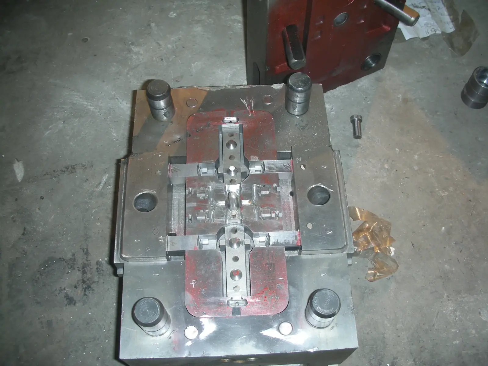
Factory or Process Image
Reserve space for a production, tooling, or inspection photo that visually supports the main topic.
Best as a wide industrial image
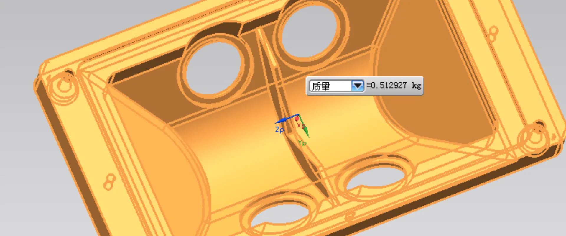
Component Detail Image
Use a close-up of a casting, surface finish, machined feature, or application component to add visual proof.
Best as a detail or macro shot
The quality of every die casting begins with the quality of its tool. A well-designed die -with optimized gating, balanced cooling, appropriate steel grade, and adequate surface finish -produces consistent, low-defect castings at high production rates. A poorly designed or maintained die produces porosity, warpage, and dimensional variation regardless of how carefully the casting process is controlled.
KastMfg's in-house tooling division designs and fabricates all dies from concept through first article sampling. We do not outsource tooling -every die is built in our 4,500 m2 tool shop on 15 dedicated CNC machining centers by our permanent tool-making staff.
Why In-House Tooling Matters
When casting and tooling are managed by separate companies, design decisions made in the tooling shop affect casting quality without the casting team's input -and vice versa. Gate location chosen for convenient machining may create porosity in a pressure-critical zone. Cooling channel layout may produce hot spots that cause warpage. These problems are difficult and expensive to fix after the die is cut.
At KastMfg, the project engineer who reviews your DFM report advises the die designer who designs the gating system who works alongside the toolmaker who cuts the steel. The casting team tests the die on their own machines. Problems are caught and corrected by the same team, on-site, without the coordination overhead and schedule penalties of inter-company escalation.
Tooling Steel Options
| Grade | Hardness | Characteristics | Best Application |
|---|---|---|---|
| H13 hot work tool steel | 44-48 HRC | High thermal fatigue resistance, long die life | Production dies for aluminum and magnesium -standard choice |
| P20 pre-hardened steel | 28-112 HRC | Faster machining, lower cost, adequate for low cycles | Prototype and short-run dies; zinc dies at lower volumes |
| S7 shock-resistant steel | 54-58 HRC | High toughness, impact resistance | Gate inserts and high-velocity erosion areas |
| H21 hot work steel | 48-112 HRC | Extreme thermal stability | Very high metal temperature applications |
| Beryllium copper inserts | - | Very high thermal conductivity | Localized rapid cooling zones in complex castings |
Die Design Process
1. Parting Line and Cavity Layout
The parting line -where the two die halves separate -is determined by the part's geometry, cosmetic requirements, and ejection direction. KastMfg's tooling engineers evaluate multiple parting line options and recommend the configuration that minimizes undercuts, optimizes surface quality on cosmetic faces, and provides the most robust ejection.
2. Gating and Runner System
Gate location and design govern how metal fills the cavity. Poor gating produces cold shuts, porosity, and flash. KastMfg designs gating to:
- Fill the cavity in a single, controlled flow front (minimizing air entrapment)
- Position gates away from pressure-critical or cosmetically sensitive surfaces
- Enable clean trimming by trim die without requiring CNC for gate removal
3. Mold Flow Simulation
Before cutting steel, KastMfg runs mold flow simulation on all new production dies. The simulation predicts:
- Fill pattern and fill time
- Air entrapment locations (guides overflow well placement)
- Temperature distribution at end of fill (identifies hot spots prone to shrinkage)
- Solidification sequence (identifies thick sections vulnerable to shrinkage porosity)
Gates and overflows are repositioned virtually until the simulation shows acceptable fill quality. This eliminates the most common causes of T1 trial failures.
4. Cooling System Design
Die temperature management is critical for cycle time, part quality, and die life. KastMfg designs cooling circuits for uniform heat extraction, targeting die face temperatures of 180-220°C for aluminum and 150-180°C for zinc. Baffles and bubblers reach into deep cores and projections where straight-line cooling channels cannot access.
5. Ejection System
Ejector pins must be sized and positioned to apply uniform force that ejects the part without distortion. For thin-wall parts or complex geometry, flat ejector blades or stripper plates are used. Ejector pin marks on cosmetic surfaces are minimized by design.
Tooling Lead Times
| Tool Type | Steel Grade | Typical Lead Time |
|---|---|---|
| Prototype (single-cavity) | P20 | 3-5 weeks |
| Production single-cavity (simple) | H13 | 5-8 weeks |
| Production single-cavity (medium complexity) | H13 | 6-8 weeks |
| Production with 1-2 slides | H13 | 7- weeks |
| Multi-cavity (2- cavities) | H13 | 7-10 weeks |
| Family tool | H13 | 7- weeks |
| Insert for existing base | H13/P20 | 2-4 weeks |
Expedited tooling (2- week prototype dies) available for time-critical programs at premium.
Expected Die Life
| Alloy | Process | Typical Die Life |
|---|---|---|
| Zinc (Zamak 3/5) | Hot chamber | 300,000 -1,000,000+ shots |
| Aluminum (A380/ADC12) | Cold chamber | 80,000 -150,000 shots |
| Magnesium (AZ91D) | Hot chamber | 100,000 -200,000 shots |
| Aluminum (A413) | Cold chamber | 60,000 -120,000 shots |
Die life depends on injection parameters, alloy chemistry, gate velocity, and maintenance frequency. KastMfg conducts scheduled die inspections at defined shot count intervals, recommending preventive maintenance (gate insert replacement, parting line grinding, cooling circuit cleaning) to maximize service life.
Tooling Ownership Policy
All tooling manufactured by KastMfg is customer-owned. This is stated explicitly in every purchase order and quotation. Upon final tooling payment, you receive:
- Complete die assembly drawings (2D and 3D where applicable)
- Bill of materials (steel grades, component specifications)
- Maintenance log (inspections, repairs, shot count history)
- Spare parts inventory (spare inserts, ejector pins)
Tools may be transferred to another facility at your instruction at any time. We provide packing and export documentation for international transfers.
Tooling Cost Factors
Tooling cost varies significantly by part complexity. The main cost drivers are:
| Factor | Low Cost | High Cost |
|---|---|---|
| Number of slides | 0 | 3+ |
| Number of cavities | 1 | 4+ |
| Part size | Small (<200 mm) | Large (>600 mm) |
| Steel grade | P20 | H13 |
| Core complexity | Simple | Complex internal passages |
| Surface finish requirement | As-machined | EDM textured, polished |
KastMfg provides itemized tooling quotations that break down the cost by component -cavity steel, slides, cooling system, ejector system, base -so customers understand exactly what they are paying for.
Related Capabilities
Tooling decisions affect every downstream step in a die casting program. Review these resources before you finalize die design:
- Aluminum die casting — production capacity and alloy options after tooling approval
- Die casting process — how gating, cooling, and trim align with tool design
- Quality control — first article, SPC, and inspection records tied to each tool
- Die casting tool transfer — onboarding dies from another supplier
Frequently Asked Questions
Can I use existing tooling from another supplier?
Yes. KastMfg can assess transferred tooling for condition and compatibility with our machines. We provide a tooling audit report with refurbishment recommendations. Most tools can be validated and running within 2-4 weeks of arrival.
What if the tool needs modification after first shots?
Tooling modifications after T1 trials are common and expected. Minor modifications -gate adjustment, overflow relocation, cooling changes -are performed on-site by our tooling team, typically within 1- days. Structural changes requiring significant steel removal or insert replacement are discussed and quoted before execution.
Do you guarantee die life?
We design and maintain dies to the standards described above and provide die life estimates based on alloy, parameters, and part geometry. Actual die life depends on production conditions. We monitor die condition at agreed intervals and recommend maintenance before quality is affected.
Tooling inquiry: yaoqingpu1983@gmail.com | +86 138 1403 4409 | No.6, Rungu Road, Nanjing, China
Related Resources
Next steps for die casting tooling
Aluminum Die Casting | A380, ADC12, A360, A413
precision aluminum die casting manufacturer with 20+ years experience. A380, ADC12, A360, and A413 parts for automotive, industrial, electronics...
ServiceDie Casting in China -Why Source from KastMfg
precision die casting manufacturer in China supplying aluminum, zinc, and magnesium die casting parts to OEM customers worldwide....
CapabilityQuality Control
Review inspection workflow, traceability support, and process control standards before launch.
Process GuideDie Casting Process
See how casting, trimming, machining, finishing, and inspection fit together in production.
Next StepRequest a Quote
Send your drawing package and target volume to get an engineering-backed quotation.
Need a Quote for Your Project?
Our engineering team is ready to review your requirements and provide competitive pricing with fast turnaround.
Request a Quote