Die Casting Defects -Causes, Types & Solutions
Complete guide to die casting defects: gas porosity, shrinkage, cold shuts, flash, misruns, soldering, warpage, and blisters -root causes...

Qingpu Yao
Process & Quality Engineering
Blog Visual Plan
Article visuals for die casting defects
These visuals use your current KastMfg image library now, and they will automatically switch to article-specific images when you add them later.
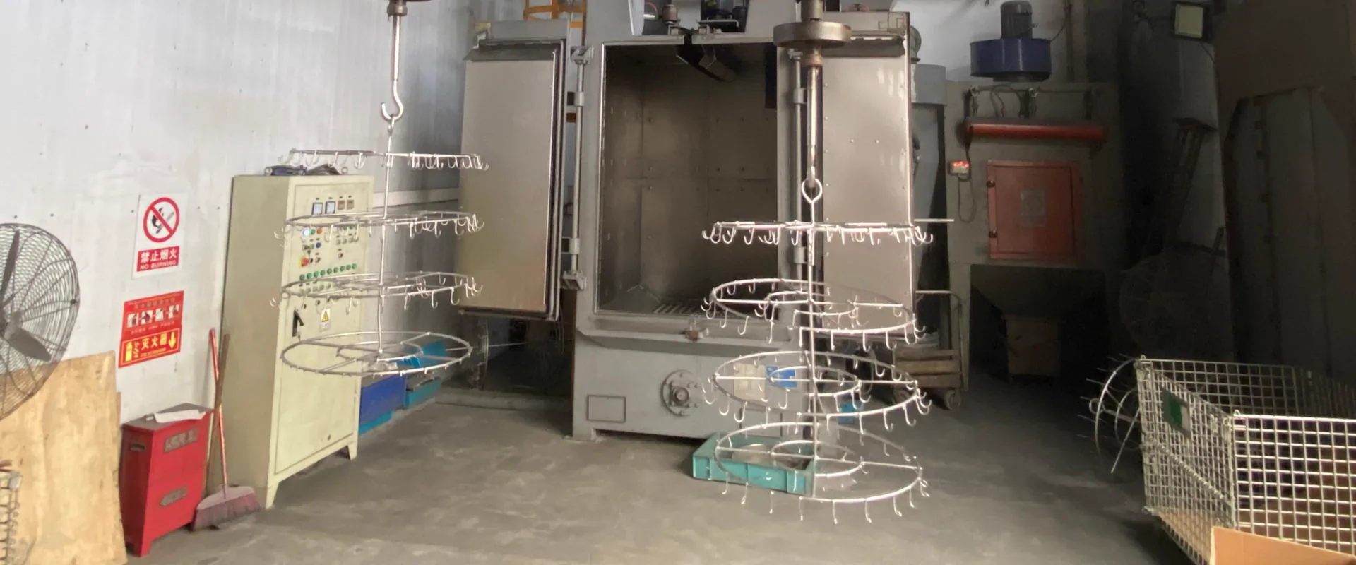
Lead Technical Image
Add a hero-level manufacturing, tooling, or component image that reinforces the article topic above the body copy.
Best as a wide industrial photo
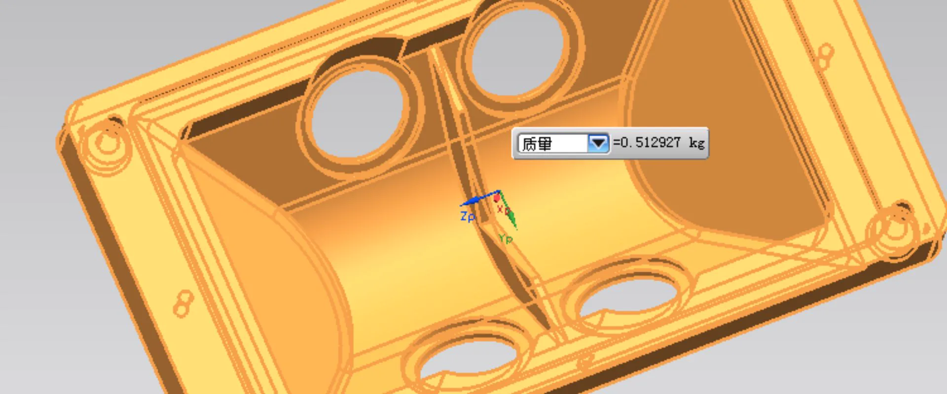
Comparison or Detail Image
Reserve a second image for an alloy comparison, defect example, tooling detail, or application close-up deeper in the article.
Best as a close-up or annotated visual
The eight most common high-pressure die casting (HPDC) defects are gas porosity, shrinkage porosity, cold shut, flash, misrun, soldering, warpage, and blister. Each defect has distinct root causes, identification methods, and prevention strategies — covered in detail below.
Understanding die casting defects is essential for engineers specifying die cast components, quality teams managing production, and buyers evaluating supplier capability. These defects are defined and classified in NADCA and ISO 8062 standards.
1. Gas Porosity
What it is: Round or irregular voids inside the casting, invisible on the surface but detectable by X-ray or visible on a polished cross-section. Gas porosity is the most common die casting defect.
How it forms: Two mechanisms:
- Air entrapment -turbulent metal flow during injection traps air that cannot escape before solidification. The high-speed injection (10-100 m/s at the gate) necessary for complete fill inherently creates turbulence.
- Dissolved hydrogen -aluminum melt absorbs hydrogen from moisture in the atmosphere and from wet or contaminated ingot. As the metal solidifies, hydrogen comes out of solution and forms porosity.
How to identify: X-ray inspection (round, bright voids against darker background). Destructive cross-section on metallographic samples. CT scanning for volumetric mapping.
Prevention:
- Vacuum-assisted die casting (VADC) removes 60-80% of cavity air before injection
- Optimized gate velocity -lower velocity reduces turbulence while maintaining complete fill
- Overflow wells positioned to capture the leading edge of flow (which contains trapped air)
- Rotary degassing of the melt before casting to remove dissolved hydrogen
- Dry, preheated ingot storage to prevent moisture absorption
When it matters: Gas porosity below a defined size and distribution is acceptable for structural and cosmetic parts. For pressure-tight components (hydraulic valves, pneumatic actuators), and for parts subject to T6 heat treatment, near-zero porosity is required.
2. Shrinkage Porosity
What it is: Irregular, branching voids concentrated in thick sections of the casting. Unlike gas porosity (round), shrinkage porosity is angular and dendritic in appearance.
How it forms: Metal contracts as it solidifies. In thick sections, the surface solidifies first while the interior is still liquid. As the interior solidifies and contracts, there is insufficient liquid metal to feed the shrinkage -resulting in voids.
How to identify: X-ray (angular, dark, branching pattern in thick sections). Visible on cross-sections. Often correlates with sections visually thicker than adjacent walls.
Prevention:
- Design uniform wall thickness -thick sections are the primary cause
- Correct die temperature profile -die sections adjacent to thick casting areas should run cooler to accelerate solidification
- Adequate intensification pressure -pushes semi-solid metal into shrinking regions
- Chill inserts in the die at thick sections to accelerate local solidification
3. Cold Shut
What it is: A visible line or seam on the casting surface where two separate flow fronts met but did not fully fuse. The metal at each flow front had partially solidified before meeting, preventing metallurgical bonding. See our dedicated cold shut guide for detailed prevention parameters.
How to identify: Visible surface line, often slightly depressed or showing a different surface texture. May be mistaken for a parting line but occurs mid-cavity, not at the die interface. Destructive cross-section shows an unbonded interface.
Prevention:
- Increase injection velocity -faster fill means both flow fronts arrive at the junction while still fully liquid
- Raise metal and die temperature -reduces premature solidification during fill
- Gate redesign -position gates to minimize flow length before fronts meet
- Increase wall thickness in areas prone to cold shut -thin walls solidify fastest
4. Flash
What it is: Thin, unwanted fins of metal at the die parting line, around ejector pin locations, or at slide interfaces. Flash is metal that has been forced into the gap between die components.
How to identify: Visually obvious -thin metallic fins along parting lines or around any die interface.
Prevention:
- Ensure clamping force is sufficient -the clamp must exceed the projected injection force across the parting line
- Die maintenance -worn parting line surfaces allow gaps to form; regular die face grinding restores flatness
- Review injection parameters -excessive peak pressure forces metal into gaps that adequate pressure would not penetrate
- Die design -parting line location and flatness tolerance specified during die design
5. Misrun (Short Shot)
What it is: The cavity does not fill completely. A portion of the casting is absent -typically at the end of flow or in thin sections that solidify before metal arrives. See the dedicated misrun and short shot guide for identification and prevention detail.
How to identify: Visually obvious -part of the cavity is simply not filled.
Prevention:
- Increase injection velocity -faster fill reaches thin sections before solidification
- Increase metal and die temperature -more thermal energy available for fill
- Add overflow wells at the end of flow -overflows create a pressure reservoir that pulls metal through thin sections
- Review gate location -long flow paths in thin walls are prone to misrun
6. Soldering (Die Erosion)
What it is: Aluminum (or zinc) bonding to the die steel surface, causing metal to stick rather than eject cleanly. Results in torn casting surfaces, pitting on the die, and ultimately die damage requiring repair. Soldering and blistering often occur together on programs requiring heat treatment.
How it forms: High gate velocity creates erosive mechanical contact between liquid metal and die steel. At high temperatures, iron in the tool steel dissolves into the aluminum melt, creating an iron-aluminum intermetallic layer that bonds casting to die.
Prevention:
- Reduce gate velocity -the primary driver of soldering is excessive velocity at the gate
- Proper die lubrication -adequate release agent application forms a thermal and chemical barrier
- High-quality die steel -H13 with proper hardness (44-48 HRC) resists erosion better than softer grades
- Soldering-resistant inserts -beryllium copper or TiAlN-coated inserts at high-velocity gate areas
7. Warpage and Distortion
What it is: The ejected casting does not conform to the drawing geometry — it is bowed, twisted, or otherwise distorted. Warpage is a dimensional non-conformance that cannot always be detected by surface inspection.
How it forms: Residual stresses from non-uniform cooling relax after ejection, distorting the part. Asymmetric cooling in the die causes one side to contract more than the other. Premature ejection before the part has sufficient strength allows ejector pin forces to distort it.
Prevention:
- Balanced cooling channels in the die -uniform heat extraction from all sections
- Correct ejection timing -allow the part to cool sufficiently before ejection
- Ejector pin layout -distribute pins to apply uniform ejection force without local stress concentration
- Fixturing during cooling for complex parts prone to stress relaxation
- Wall thickness uniformity in design -the root cause of most warpage is uneven wall thickness
8. Blister
What it is: A subsurface gas bubble that does not break through the surface during casting but expands during subsequent heat treatment or elevated-temperature service, raising the surface into a visible blister. Prevention overlaps with soldering and blistering on T6 programs.
How it forms: Gas porosity close to the casting surface. During T6 heat treatment (solution treatment at 480-520°C for aluminum), the gas inside the pore expands, and the thin surface skin deforms outward.
Prevention:
- Reduce subsurface porosity through VADC and optimized injection parameters
- Shot peening of the casting surface before heat treatment compresses the skin, making it more resistant to blister formation
- Vacuum pressure impregnation (VPI) seals near-surface porosity before heat treatment
- For programs where T6 is required, VADC or LPDC should be specified during program planning
Defect Summary Reference
| Defect | Appearance | Primary Cause | Key Prevention |
|---|---|---|---|
| Gas porosity | Round voids (X-ray) | Air entrapment, dissolved H2 | VADC, degassing, optimize gate velocity |
| Shrinkage porosity | Angular voids in thick sections | Insufficient feeding | Uniform walls, intensification, chills |
| Cold shut | Surface seam or line | Low temperature or velocity | Increase injection speed and temperature |
| Flash | Fin at parting line | Insufficient clamp, worn die | Increase clamp force, die maintenance |
| Misrun | Incomplete fill | Low velocity, temperature, or thin walls | Increase velocity, add overflows |
| Soldering | Metal sticking to die | High gate velocity, poor lubrication | Reduce velocity, proper lubrication |
| Warpage | Dimensional distortion | Non-uniform cooling, early ejection | Balanced cooling, ejection timing |
| Blister | Surface bubble after heat treatment | Near-surface gas porosity | VADC, impregnation, shot peen |
Quality concerns about a current supplier? Contact KastMfg: yaoqingpu1983@gmail.com | +86 138 1403 4409
About The Author
Qingpu Yao on die casting defects
Process & Quality Engineering
Focuses on DFM, tooling behavior, defect prevention, inspection planning, and production controls that affect yield and downstream machining stability.
Related Reading
Keep exploring the blog
Testing for Porosity in Die Castings - X-Ray, CT, Le...
Die casting porosity testing checks whether internal voids, gas pores, shrinkage cavities, or connected porosity will affect strength, machining, sealing, pressure tightness, or...
Qingpu Yao
8 min read
Aluminum Die Casting Electronics Enclosures Guide
Aluminum die casting for electronics enclosures is used when a housing needs mechanical protection, EMI shielding, heat dissipation, gasket sealing, connector features, and repe...
Qingpu Yao
4 min read
Die Casting vs Gravity Casting -Process & Cost Compa...
High-pressure die casting and gravity casting both use metal molds, but they fill those molds in very different ways. High-pressure die casting injects molten metal into the die...
Qingpu Yao
3 min read
H13 vs P20 Die Casting Tooling Steel - When to Use Each
H13 and P20 are both tool steels, but they are not equal choices for die casting. H13 is the standard for production die casting cavities because it handles thermal fatigue, hea...
Qingpu Yao
6 min read