Industrial Machinery Die Casting
precision die casting components for industrial machinery: hydraulic manifolds, valve bodies, motor housings, gearbox covers, compressor crankcases...
Supporting Visuals
Supporting visuals for industrial die casting
These images are pulled from your current KastMfg asset library. Page-specific files automatically override shared fallback visuals when you add them later.
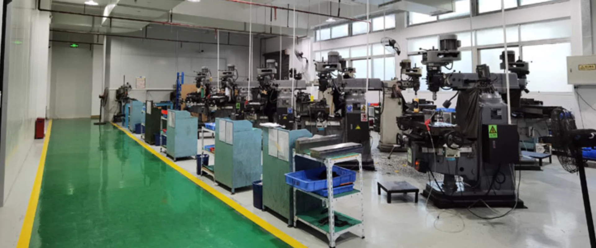
Factory or Process Image
Reserve space for a production, tooling, or inspection photo that visually supports the main topic.
Best as a wide industrial image
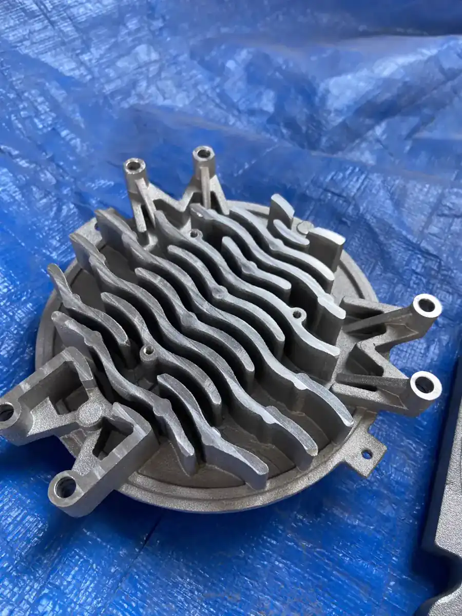
Component Detail Image
Use a close-up of a casting, surface finish, machined feature, or application component to add visual proof.
Best as a detail or macro shot
Industrial machinery is one of die casting's most demanding application sectors. Unlike automotive parts -which follow well-defined OEM quality systems -industrial machinery components span an enormous range of operating conditions, performance requirements, and quality frameworks. A hydraulic manifold block operating at 350 bar in a steel mill press has almost nothing in common with a small pneumatic valve body in a packaging machine, yet both are die cast aluminum parts that require the same fundamental process discipline: correct alloy selection, controlled injection parameters, verified internal soundness, and dimensional accuracy backed by measurement data.
KastMfg has supplied die cast components to industrial machinery OEMs, system integrators, and fluid power manufacturers for over 20 years. Our industrial customer base ranges from specialty machine builders producing 500 units per year to global hydraulic component manufacturers shipping tens of millions of valve bodies annually. Both receive the same technical rigor -and the same direct access to a project engineer who reads their drawing and knows their application.
This guide covers the full breadth of industrial die casting applications we serve, the technical requirements specific to each, and how KastMfg's integrated facility addresses them.
1. Hydraulic Systems -The Most Demanding Industrial Application
Hydraulic components represent the most technically challenging segment of industrial die casting. Operating pressures routinely exceed 200-250 bar in industrial systems; leakage is a functional failure, not merely a quality defect; and the dimensional requirements for port faces, bore diameters, and thread forms are tight enough that post-casting machining is always required.
What Makes Hydraulic Die Casting Difficult
The fundamental challenge is porosity. Standard high-pressure die casting (HPDC) injects metal at 20-60 m/s at the gate, creating turbulent flow that entrains air. This gas cannot fully escape before solidification, leaving distributed porosity of 0.1- mm diameter throughout the casting. For structural brackets or enclosures, this level of porosity is inconsequential. For a hydraulic manifold with internal passages at 300 bar, an interconnected pore network between a passage and the exterior surface is a leak path -and a product failure.
How KastMfg Achieves Hydraulic-Grade Castings
Alloy selection -A413 as standard for hydraulic applications
KastMfg specifies A413 (near-eutectic aluminum, 12% silicon) for hydraulic manifolds and valve bodies. At the eutectic composition, aluminum-silicon alloy solidifies with the finest possible microstructure -finer dendritic spacing, finer inter-dendritic porosity, lower total shrinkage than hypoeutectic alloys like A380. The result is fewer, smaller, and less interconnected pores. A413 also has slightly higher thermal conductivity (121 vs 96 W/m·K for A380), beneficial for dissipating heat in hydraulic circuit housings.
Vacuum-assisted die casting (VADC)
For qualifying hydraulic programs, KastMfg operates vacuum-assisted HPDC on dedicated machines. A vacuum pump evacuates the die cavity and runner system immediately before injection, drawing cavity pressure below 50 mbar. Incoming metal displaces evacuated air rather than compressing it -reducing gas porosity by 60-70% versus standard HPDC. VADC parts typically show ASTM E505 Class 1 or Class 2 porosity on X-ray, sufficient for rated working pressures of 60-150 bar without impregnation. For pressures above 200 bar, VADC plus vacuum pressure impregnation (VPI) is the standard approach.
Mold flow simulation before tooling
Gate location is more critical for hydraulic castings than for any other application. Poor gate placement creates weld lines at passage intersections -exactly where the casting must seal under pressure. KastMfg runs mold flow simulation on every hydraulic tooling program, optimizing gate position to avoid weld lines at pressure-critical surfaces, positioning overflows to capture cold metal at the end of flow, and validating that fill speed achieves complete cavity fill without excessive turbulence.
100% pressure testing
All hydraulic and pneumatic castings produced for KastMfg customers are 100% pressure-tested per the customer's specification. Standard test protocols use air decay at 1.5x rated working pressure with 30-second hold and leak rate limit of <5 cm3/min. Helium mass spectrometry is available for ultra-low leak rate requirements (<10^-7 mbar·L/s). Test records are archived by part serial number and provided with every shipment.
Hydraulic Parts Produced at KastMfg
| Part Type | Typical Alloy | Typical Working Pressure | Key Features |
|---|---|---|---|
| Directional control valve bodies | A413 | 100-150 bar | Multiple port faces, spool bore, solenoid mounting |
| Hydraulic manifold blocks | A413 + VADC | 200-250 bar | Multiple circuit passages, SAE/CETOP port patterns |
| Hydraulic pump housings | A380 or A413 | 100-150 bar | Bearing bores, shaft seal land, port connections |
| Filter housings | A380 | 10-20 bar | Thread form, bypass valve seat, differential pressure port |
| Accumulator end caps | A413 | 100-200 bar | Pressure-tight, thread form, gas valve port |
| Pressure regulator bodies | A413 | 50-150 bar | Precision spool bore, adjustment thread, port faces |
| Flow divider bodies | A413 | 100-200 bar | Multiple bores, tight bore-to-bore alignment |
2. Pneumatic Systems -Precision at Scale
Pneumatic components operate at lower pressures (4-6 bar) but compensate with extraordinary production volumes and tighter dimensional requirements. A pneumatic solenoid valve body may be produced at 2- million pieces per year; every one must pass a 10-second leak test before leaving the factory. This combination of volume and quality requirement makes pneumatic valve die casting one of the most process-disciplined segments of the industry.
Pneumatic Valve Body Requirements
Bore concentricity and cylindricity: The spool bore in a pneumatic directional valve must be cylindrical to within 0.01-0.02 mm over its length, and concentric with the port faces to within 0.05 mm. This is achievable by casting the bore slightly undersized and finish-boring in CNC after casting -but only if the casting provides sufficient and consistent machining stock, and only if the casting is dimensionally stable enough not to distort during machining.
Port face flatness: Port faces that mount to manifold blocks or sub-bases must be flat to 0.02-0.05 mm over the sealing area. Cast flatness is rarely adequate; face milling on CNC after casting is standard.
Wall thickness uniformity: Thin-wall sections of pneumatic valve bodies (1.5-2.5 mm typical) must be uniform to avoid porosity in thick-to-thin transitions. KastMfg's DFM review specifically evaluates wall thickness variation and recommends ribs or core reductions to improve uniformity before tooling is committed.
High-volume consistency: At 2 million+ pieces per year, even a 0.1% porosity failure rate generates 2,000 defective parts per year. KastMfg's SPC-controlled process targets Cpk >=1.67 on all critical dimensions for high-volume pneumatic programs, backed by 100% leak test.
Pneumatic Parts Produced at KastMfg
- Solenoid valve bodies (2/2, 3/2, 5/2, 5/3 -various ISO port sizes)
- Pneumatic cylinder end caps and front/rear flanges
- Cylinder barrel end closures and tie-rod nuts
- Air preparation unit bodies (filter/regulator/lubricator housings)
- Pneumatic quick-exhaust valve bodies
- Vacuum generator bodies and ejector housings
- Pneumatic positioner and controller housings
3. Electric Motors and Drives -Thermal, Structural, and Finishing Requirements
Electric motor housings and drive enclosures are among the highest-volume industrial die casting applications. The global motor market produces billions of units per year; virtually every NEMA and IEC frame motor uses die cast aluminum end shields and, for smaller frames, a die cast aluminum stator frame.
Motor End Shield Requirements
Motor end shields must simultaneously satisfy structural, thermal, dimensional, and surface requirements:
Bearing bore accuracy: The bearing bore in a motor end shield is the most critical dimension in the part. It must be cylindrical to H6/H7 tolerance (typically +/-0.008-0.015 mm on bore diameter), perpendicular to the mounting face to within 0.02-0.05 mm, and free of porosity or surface defects that could affect bearing seating. KastMfg bores all motor bearing housings on dedicated CNC boring machines with measurement verification after every component.
Rabbet fit: The spigot (rabbet) that locates the end shield on the stator frame must be concentric with the bearing bore within tight limits (typically 0.03-0.05 mm total indicator runout). In die casting, the rabbet is cast to near-finished size and finish-turned or bored on CNC. KastMfg's integrated casting-to-machining workflow maintains consistent datum relationships between the bearing bore and rabbet.
Thermal performance: Aluminum end shields contribute significantly to motor cooling by conducting heat from the bearing and winding end-turn region to the outer surface. A380 and A360 alloys are standard choices; A360's higher thermal conductivity (113 W/m·K vs 96 W/m·K for A380) is occasionally specified for high-efficiency motor programs.
ATEX and IP rating compliance: Motors for hazardous environments require IP65/IP66 sealing with machined O-ring grooves in the end shield sealing faces. IP54/IP55 housings require carefully designed drainage provisions cast into the end shield geometry. KastMfg's DFM team reviews sealing requirements and designs the cast O-ring groove geometry as part of the tooling scope.
Motor and Drive Parts Produced at KastMfg
| Part | Frame Size Equivalent | Alloy | Key Machined Features |
|---|---|---|---|
| End shields (DE + NDE) | NEMA 56-149T / IEC 63-115 | A380, A360 | Bearing bore H6, rabbet, mounting holes |
| Fan covers | NEMA 56-84T | A380 | Ventilation slots (cast), mounting tabs |
| Terminal box bodies | All frames | A380 | Cable entry boss, mounting feet |
| VFD / servo drive enclosures | - | A380 | Heatsink fin geometry, DIN rail mounts |
| Motor adaptor flanges | All | A380 | Pilot bore, bolt circle, face flatness |
4. Gearbox and Power Transmission -Sealing, Alignment, and Load
Gearbox housings, reducer covers, and worm gear cases impose a unique combination of requirements on die casting: the housing must hold gear and bearing alignment under load (stiffness), seal lubricating oil over years of service (pressure tightness and mating face quality), and withstand the shock loading of reversals and overloads (impact toughness).
Gearbox Housing Design Considerations
Bearing bore alignment: In a parallel-shaft gearbox, the center distance between input and output shaft bearing bores directly determines gear mesh quality, noise level, and gear life. KastMfg machines paired bearing bores in a single setup on horizontal machining centers (HMC) with rotary table, maintaining center distance to +/-0.03-0.05 mm and bore parallelism to 0.02 mm/100 mm.
Parting line sealing: The gearbox housing splits at a parting plane that must seal against oil leakage -a challenge in die casting because the parting line is also a flash line, and perfect flatness across the parting face is not guaranteed by casting alone. KastMfg face-mills all gearbox parting faces to 0.02 mm flatness, and the mating cover face is similarly machined, enabling reliable oil sealing with liquid gasket or a defined-compression O-ring.
Wall stiffness at mounting feet: Gearbox mounting feet are stress concentration points subject to fatigue in vibrating installations. KastMfg evaluates rib geometry at mounting foot roots during DFM and specifies minimum fillet radii (typically 3- mm) at all mounting foot transitions to extend casting fatigue life.
Oil fill, drain, and vent provisions: Every gearbox housing requires oil fill, level, drain, and vent ports. These are standard features reviewed during DFM for casting feasibility, thread size, and location relative to the parting line.
Gearbox and Transmission Parts Produced at KastMfg
- Parallel shaft gearbox housings (worm, helical, bevel-helical)
- Worm reducer housings and covers
- Right-angle gearbox housings
- Variator and CVT housing components
- Torque converter housings
- Clutch and brake housing covers
- Bearing retainer plates and adapter flanges
5. Industrial Automation -Lightweight Precision for Robotics and Handling
Industrial automation is one of the fastest-growing segments for die casting. Collaborative robots (cobots), articulated arms, SCARA robots, and linear transfer systems all use die cast aluminum structural components throughout their kinematic chains. The requirements are demanding: low weight (every gram at the end of a robot arm increases the required motor torque and reduces payload), high stiffness (deformation under load affects positioning accuracy), and tight geometric tolerances on interface features (bolt patterns, locating bores, and mounting faces).
Robot and Automation Component Requirements
Weight reduction without stiffness loss: KastMfg's tooling team works with automation OEM engineers to optimize rib geometry, coring patterns, and wall thickness distributions for maximum stiffness-to-weight ratio. Topology-optimized cast structures that would be impossible to achieve by machining from billet are standard die casting practice.
Tight GD&T on interface features: Robot arm links must bolt together with consistent geometry across all production units. KastMfg machines all interface features (locating bores, bolt hole patterns, mating faces) in a single CNC setup per part to eliminate datum stacking errors. CMM verification of all GD&T callouts is standard for automation programs.
Cable routing provisions: Modern robot arms integrate cable, pneumatic, and signal conduits through the arm structure. Die casting can incorporate cast channels and entry/exit ports in the structural geometry. KastMfg reviews cable routing provisions during DFM and recommends cast-in provisions that simplify assembly while not compromising the structural integrity of the arm section.
Anodizing for wear resistance: Robot arm surfaces that contact guides, cables, or tooling are often Type III hard-anodized (25-100 μm, 60+ HRC equivalent) for wear resistance. KastMfg's in-house anodizing capability covers both Type II and Type III for automation components.
Automation Parts Produced at KastMfg
- Articulated robot arm links (shoulder, elbow, wrist)
- SCARA robot arm segments
- Linear axis carriage bodies and slide components
- End-of-arm tooling (EOAT) structural frames
- Gripper jaw bodies and actuator housings
- Vision system mounting brackets and camera housings
- Encoder and servo motor mount housings
6. Compressors and Air Tools -High-Cycle Fatigue and Thermal Demands
Compressor crankcases and air tool housings are subject to cyclic pressure loading (compressors) or cyclic impact loading (air tools), both of which make fatigue resistance a primary design criterion. KastMfg addresses these requirements through alloy optimization, porosity minimization, and -where required -T5 or T6 heat treatment.
Compressor Casting Requirements
Compressor crankcases must contain pressure cycling (in reciprocating compressors, every shaft revolution produces a pressure pulse), maintain bearing alignment under load, and seal oil and refrigerant without leakage over years of continuous operation. For reciprocating and scroll compressors, the preferred alloy is A380 or ADC12 with vacuum-assisted casting for the crankcase, and A413 for valve plate and head components where pressure tightness is paramount.
For hermetic refrigeration compressors operating with refrigerant charge, material compatibility with the refrigerant and lubricating oil is also a consideration -A380 and ADC12 have established compatibility data with common refrigerants.
Air Tool Housing Requirements
Pneumatic impact tools and grinders are subject to the highest vibration and shock loading of any die casting application. The housing must withstand hundreds of millions of impact cycles over the tool's service life. KastMfg specifies A380 for most air tool housings, with T5 aging treatment for programs requiring improved fatigue strength. All housing wall thickness transitions receive generous fillets during DFM review to reduce stress concentration factors.
Compressor and Air Tool Parts Produced at KastMfg
- Reciprocating compressor crankcases
- Scroll compressor crankcase bodies
- Refrigeration compressor valve plates (A413)
- Air compressor head covers
- Pneumatic angle grinder housings
- Pneumatic impact wrench housings
- Air ratchet and drill housings
- Pneumatic nailer bodies
Material Selection Guide for Industrial Die Casting
Selecting the right alloy is the single most important technical decision in an industrial die casting program. The wrong alloy -A380 where A413 is needed for pressure tightness, or standard HPDC where VADC is required -creates quality problems that cannot be fixed by process adjustments.
| Application Category | First Choice | Alternative | Avoid |
|---|---|---|---|
| Hydraulic manifolds (>200 bar) | A413 + VADC | A413 + VPI impregnation | A380 without VADC |
| Hydraulic valve bodies (<150 bar) | A413 | A380 with VADC | Standard A380 HPDC |
| Pneumatic valve bodies | A380 or Zamak 5 | A360 | - |
| Motor end shields | A380 | A360 (thermal priority) | - |
| Gearbox housings | A380 | A380 + T5 | - |
| Robot arm links | A380 | A360 | - |
| Compressor crankcases | A380 or ADC12 | A380 + T5 | - |
| Compressor valve plates | A413 | A413 + VADC | A380 |
| Air tool housings | A380 | A380 + T5 | - |
| Small precision pneumatic parts | Zamak 5 | Zamak 3 | - |
Post-Casting Operations: From Casting to Ready-to-Install Component
Industrial machinery customers rarely want raw castings. They want finished, tested, assembled components that arrive ready for installation. KastMfg's integrated facility delivers all post-casting operations in-house.
CNC Machining for Industrial Components
KastMfg's 18 machining centers (3-axis through 5-axis) perform all secondary machining operations required for industrial components:
Hydraulic components: Port face milling to 0.01 mm flatness -> Spool bore finish boring to H6/H7 -> Port thread milling (BSPP, NPT, SAE O-ring boss, CETOP) -> Mounting hole drilling and tapping -> Passage drilling for interconnected circuits
Motor components: Bearing bore boring to H6 with perpendicularity control -> Rabbet turn/bore with concentricity to bearing bore -> Face milling of mounting flanges -> Terminal box and conduit hole drilling
Gearbox components: Paired bearing bore boring in single setup (center distance control) -> Parting face milling for oil sealing -> Oil fill/drain/vent port drilling and tapping -> Mounting foot hole drilling
Surface Finishing for Industrial Components
| Finish | Industrial Application |
|---|---|
| Shot blasting | Universal preparation; functional appearance on unpainted castings |
| Powder coating | Motor housings, gearbox covers, outdoor equipment -color coding, corrosion protection |
| E-coating | Complex internal surfaces on motor housings; uniform coverage in recesses |
| Anodizing Type II | Aluminum components requiring electrical insulation or corrosion resistance |
| Anodizing Type III | Robot arm wear surfaces, precision guide surfaces |
| Chromate conversion | Electronic components requiring conductivity and adhesion promotion |
Pressure and Leak Testing
KastMfg operates pressure testing equipment in-house for hydraulic and pneumatic components:
- Air decay testing: Standard for pneumatic components (4-6 bar) and low-pressure hydraulics
- Nitrogen testing: Clean dry nitrogen for all pressure-critical castings; no moisture risk
- Helium mass spectrometry: For ultra-low leak rate requirements in sealed systems
- Hydrostatic testing: Available for burst pressure qualification
Test records -date, part serial number, test pressure, hold time, result -are archived electronically and available on demand.
Quality System for Industrial Programs
Industrial machinery OEMs have diverse quality requirements -some work to ISO 9001, others to sector-specific standards, some have proprietary supplier quality manuals. KastMfg's quality system is designed to accommodate this variety.
ISO 9001:2015 certification is the foundation. Our quality management system covers all production activities from incoming material through outgoing inspection, with documented procedures for CAPA, calibration, training, and customer complaints.
First Article Inspection (FAI): Every new or changed industrial program receives a full first article inspection: 100% dimensional layout on CMM, material certification (OES spectrometry report), process parameter documentation, and pressure test results where applicable. FAI packages are tailored to customer format requirements.
Statistical Process Control (SPC): Critical dimensions on high-volume industrial programs are monitored with SPC. Control charts are maintained throughout each production run. Out-of-control signals trigger immediate hold and investigation before production continues.
Material traceability: Every production batch is traceable to a specific melt (alloy chemistry report) and production shift (process parameter log). In the event of a field issue, KastMfg can identify all parts from the same melt and production conditions within 24 hours.
The KastMfg Industrial Advantage: 20 Years, One Roof
Industrial machinery customers have been burned by the multi-supplier model: a casting arrives from the casting house, gets lost in transit to the machining shop, comes back dimensionally non-conforming because the machiner used the wrong datum, gets returned, the root cause takes three parties to resolve, and the schedule is now four weeks late. KastMfg eliminates this scenario by performing every operation under one roof and placing one project engineer accountable for your complete component.
20+ years industrial supply experience. Our engineers have seen hydraulic valve designs fail leak test due to gate-induced weld lines at port intersections. They have seen gearbox housings warp from non-uniform die cooling. They have seen motor end shields produce bearing noise from elliptical bores caused by asymmetric ejector pin layout. This experience is embedded in our DFM review process -we catch these issues before tooling is cut, not after.
Integrated facility, single point of contact. Tooling design ->casting °CNC machining ->pressure testing ->surface finishing ->inspection ->shipping. One project engineer. One schedule. One quality record.
Scalability from development to volume. The same facility and team that produces your 500-piece development program produces your 500,000-piece production program. No supplier transition, no re-qualification, no knowledge loss.
Frequently Asked Questions
What is the maximum working pressure KastMfg hydraulic castings can achieve?
With A413 alloy and vacuum-assisted die casting (VADC), KastMfg-produced hydraulic manifolds have been qualified to 350-420 bar burst pressure in customer hydraulic test rigs. Rated working pressure (typically 1/4 of burst by hydraulic design convention) of 80-100 bar is standard; higher working pressures are achievable for specific applications. Provide your test specification -burst pressure, proof pressure, and working pressure -and we confirm capability during DFM review.
Do your motor end shields meet IEC or NEMA frame standards?
Yes. KastMfg machines motor end shields to customer-supplied drawings that reference IEC 60072, NEMA MG1, or customer-proprietary frame specifications. We do not stock catalog end shields -every part is produced to your specific drawing. Bring your frame drawing and we will provide a complete DFM review and quotation within 48 hours.
Can you produce castings for ATEX Zone 1 / Zone 2 hazardous area equipment?
We produce castings for equipment that the end customer certifies for ATEX compliance. Our role is to produce castings that conform precisely to the drawing -including the tolerances on flame path dimensions, sealing face finishes, and enclosure wall thickness. We do not perform ATEX certification ourselves, but we provide the dimensional reports and material certifications that the certification body requires.
How do you handle engineering changes on long-running industrial programs?
Engineering changes on active programs are managed through a formal change control process. The customer submits a revised drawing; our project engineer reviews the change for impact on tooling, process parameters, and inspection plan; we provide a change cost and lead time estimate; on approval, we implement the change, re-qualify the affected features, and submit a revised FAI for changed dimensions. Production from the new configuration is clearly segregated from old-configuration stock.
What is your typical lead time for industrial die casting programs?
Initial tooling lead time is 5-8 weeks for single-cavity production dies and 7-10 weeks for complex multi-slide tools. First article sampling follows within 1-2 weeks of tooling completion. Production lead times after FAI approval are typically 4-6 weeks depending on part complexity and order volume. For urgent programs, expedited tooling (3-5 weeks) is available at premium.
Can you supply small quantities for prototype and development phases?
Yes. KastMfg produces prototype quantities of 50-500 pieces using P20 prototype tooling at reduced tooling cost (typically 30-40% lower than H13 production tooling). Prototype parts are produced in the same alloy and by the same casting process as the production intent -not by CNC machining or 3D printing -giving you representative material properties and process-related features (flash lines, gate marks, as-cast surface) for design validation.
Industrial machinery inquiry: yaoqingpu1983@gmail.com | +86 138 1403 4409 | No.6, Rungu Road, Nanjing, China
Related Resources
Next steps for industrial die casting
EV Die Casting | Aluminum Motor & Battery Parts
precision aluminum die casting for electric vehicles: motor housings, inverter enclosures, battery tray structures, OBC housings...
IndustryDie Casting for LED Lighting | Heat Sink Housings
precision aluminum die cast LED lighting components: streetlight housings, high-bay fixtures, floodlights, and heat sink bodies....
Industry HubAll Industries
Browse automotive, electronics, lighting, and industrial die casting applications.
Case StudyCase Studies
See how similar programs were delivered across materials, tolerances, and export requirements.
CapabilityQuality Control
Review inspection workflow, traceability support, and process control standards before launch.
Process GuideDie Casting Process
See how casting, trimming, machining, finishing, and inspection fit together in production.
Need a Quote for Your Project?
Our engineering team is ready to review your requirements and provide competitive pricing with fast turnaround.
Request a Quote