Flash in Die Casting -Causes, Acceptable Limits & Pr...
Flash (fins at parting lines) in die casting: why it forms, acceptable flash thickness limits by application...
Supporting Visuals
Defect reference visuals for die casting flash
These images are pulled from your current KastMfg asset library. Page-specific files automatically override shared fallback visuals when you add them later.
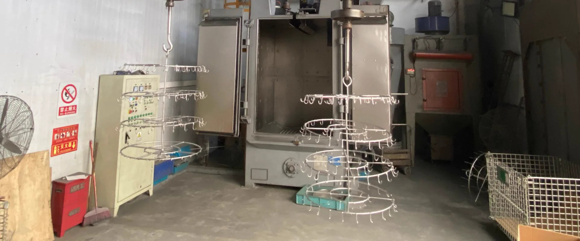
Defect Example Image
Reserve one clear defect photo, X-ray, CT scan, or sectioned sample that visually identifies the defect being discussed.
Best as a technical reference image
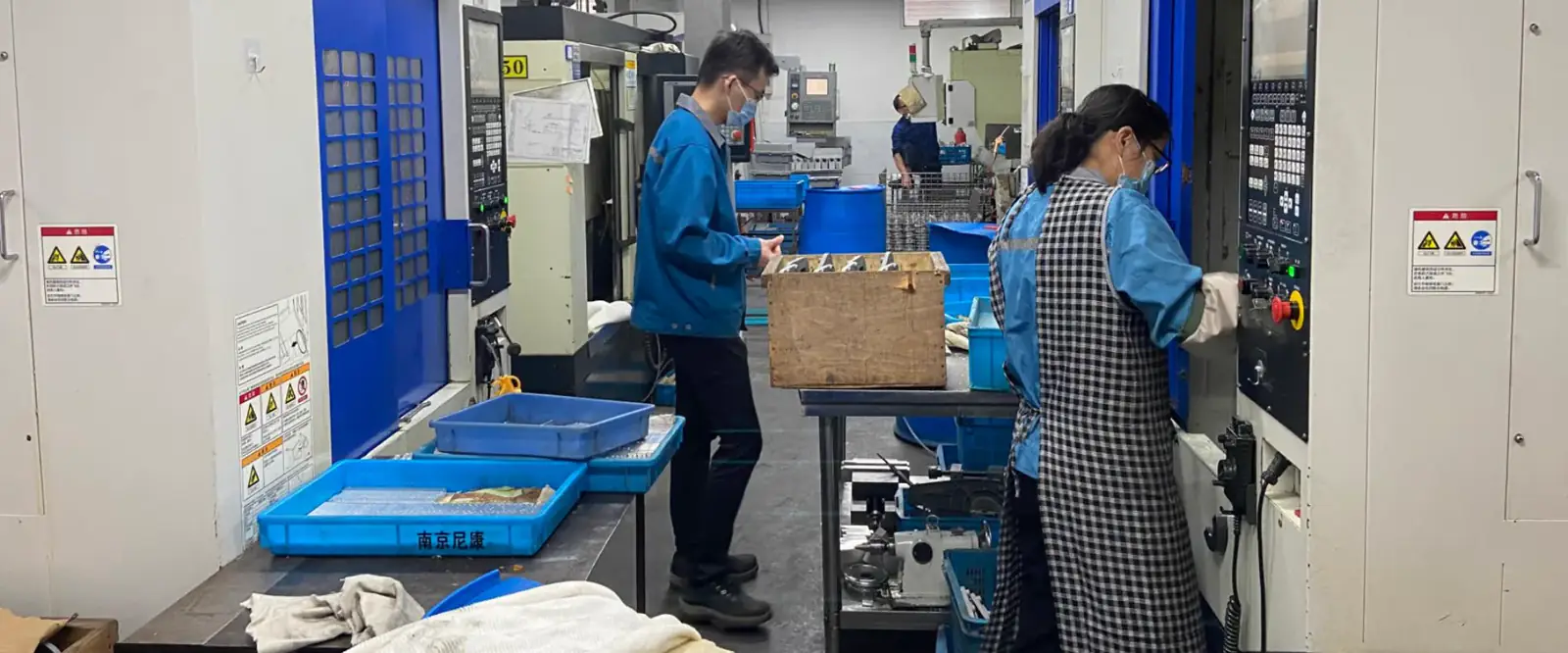
Corrective Action Image
Use a second image for tooling changes, gating adjustments, leak testing, or inspection steps that show how the defect is controlled.
Best as a process-improvement photo
Flash is the thin fin of metal that forms at die component interfaces during injection. Unlike most die casting defects, flash is not an internal quality issue -it is a surface feature that is inherent to the die casting process at some level, managed rather than eliminated. The distinction between acceptable flash (a thin, easily trimmed fin) and excessive flash (thick fins requiring rework, or flash in functional areas) determines whether flash is a minor nuisance or a production quality problem.
What Flash Is and Where It Forms
Flash forms wherever there is a gap between die components at the time of injection. Under the high injection pressure of HPDC (35-75 MPa for aluminum), even a gap of 0.02-0.05 mm allows metal to penetrate and solidify as a thin fin.
Locations where flash predictably occurs:
- The parting line (where the two die halves meet)
- Around slide interfaces (where side-pull slides contact the cavity)
- At ejector pin locations (where pins enter the cavity)
- At core pin bases (where fixed cores enter the cavity half)
Parting line flash is the most common and most visible. Even a well-maintained die will produce some parting line flash -typically 0.05-1.2 mm thick after trim die removal -because the die clamping force cannot eliminate micro-gaps under injection pressure.
Why Flash Forms -Three Mechanisms
Mechanism 1: Insufficient Clamping Force
The most straightforward cause. Injection pressure acting over the projected cavity area creates a force trying to open the die (separating force). If this separating force exceeds the clamping force, the die opens slightly during injection -creating a gap that metal fills as flash.
Separating force calculation: F_separate = Mean cavity pressure (MPa) x Projected area (cm2) / 100 tonnes
For a cavity with 200 cm2 projected area at 60 MPa mean pressure: F_separate = 60 x 200 / 100 = 120 tonnes
If the die is mounted on a 100T machine, the machine cannot maintain clamping -flash results. The machine is undersized for this cavity.
Mechanism 2: Worn Parting Line
Even a correctly sized machine cannot eliminate flash if the die's parting faces are worn, scored, or not flat. The parting line sealing area wears with each thermal cycle and each time the casting is ejected while partially adhering to one die face. Over time, micro-pitting and thermal fatigue marks on the parting face create gaps that generate flash even at adequate clamping force.
KastMfg addresses this through scheduled parting face maintenance -parting face grinding at defined shot count intervals (every 30,000 shots for aluminum, every 100,000 shots for zinc) -restoring flatness before flash deteriorates to unacceptable levels.
Mechanism 3: Excessive Injection Pressure or Velocity
High injection pressure increases the separating force above what the machine's clamping force can resist at the parting line. High injection velocity creates hydraulic hammer effects that briefly exceed the nominal separating force calculation.
Process optimization -finding the minimum injection velocity and pressure that still achieves complete fill -minimizes flash risk while maintaining part quality.
Acceptable Flash Thickness -By Application
Flash is not a zero-tolerance defect. The question is whether the flash that remains after trimming:
- Exceeds the functional tolerance for the application
- Is removable without damage to the part or unacceptable cycle time
| Application | Acceptable Parting Line Flash (After Trim) | Note |
|---|---|---|
| General structural parts | <=0.5 mm | Standard industrial tolerance |
| Functional surfaces (sealing faces) | 0 mm | Machine these surfaces -do not rely on trim |
| Cosmetic/visible surfaces | <=0.15 mm | May require vibratory finishing |
| Chrome/nickel plated zinc | <=0.10 mm | Flash visible under plating if thicker |
| Bearing or precision bore areas | 0 mm | Never locate parting line at precision bores |
| Threaded areas | 0 mm | Parting line through threads creates flash in threads |
Flash vs Parting Line Mismatch -Not the Same
Flash (thin fin of metal) and parting line mismatch (one die half displaced relative to the other) are two different defects often confused because both produce visible marks at the parting line.
Flash: A thin protruding fin. Caused by a gap between the die faces. Removed by trimming or grinding.
Mismatch: One half of the casting is offset from the other by 0.1-0.5 mm at the parting line. Caused by die alignment pins wearing, die warping, or machine platen misalignment. Cannot be removed by trimming -it changes the shape of the casting.
Identifying which defect is present:
- If the fin can be pressed flat or removed, it is flash
- If the step remains after flash removal, it is mismatch
Flash in Specific Die Casting Features
Ejector Pin Flash
Ejector pins pass through the ejector half of the die. If the pin-to-hole clearance exceeds 0.02-0.05 mm (due to wear or incorrect pin sizing), metal flows around the pin and solidifies as a ring or nipple of flash at each ejector pin location.
In functional terms, ejector pin flash is a cosmetic issue on non-functional surfaces. If ejector pins are located on sealing faces or precision mating surfaces (poor die design), the flash becomes a functional defect.
KastMfg designs ejector pin locations away from functional surfaces, documented in the control plan at program launch.
Slide Interface Flash
Side-pull slides must seal against the cavity surface to prevent flash at the slide-cavity interface. As slides wear, the sealing surface degrades and flash begins to form at slide edges.
Slide flash is typically thicker than parting line flash (because slide contact pressures are lower than the full die clamping force) and may form on surfaces that are functional -a slide face may be a visible exterior surface or a sealing face. Slide maintenance (re-machining the sealing surface) is required when slide flash exceeds specification.
Flash Prevention -Design and Process
Correct machine selection: Machine clamping force >=1.2x calculated separating force as minimum. KastMfg calculates this for every new program during quoting.
Parting line location: Position the parting line on non-functional, non-cosmetic surfaces where possible. A parting line on a sealing face or chrome-plated surface creates persistent quality problems; a parting line on a mounting lug edge is a minor trimming operation.
Scheduled die maintenance: Parting face grinding at defined intervals restores flatness before flash deteriorates. KastMfg's maintenance schedule: aluminum dies every 30,000 shots, zinc every 100,000 shots.
Minimum effective injection pressure: Use the lowest injection pressure that achieves complete fill. Higher pressure = more flash. Process optimization targets minimum pressure.
Trim die design: A well-designed trim die removes parting line flash and overflow metal in a single press stroke, producing a consistent trim line. Poor trim die design leaves flash remnants or causes die marks near the parting line.
Flash analysis and process consultation: yaoqingpu1983@gmail.com | +86 138 1403 4409 | No.6, Rungu Road, Nanjing, China
Related Resources
Next steps for die casting flash
Gas Porosity in Die Casting -Causes, Detection & Pre...
Complete guide to gas porosity in die casting: how it forms, how to detect it (X-ray, CT, cross-section), what ASTM E505 classes mean...
Defect GuideDie Casting Soldering & Blistering -Causes and Preve...
Soldering (die erosion) and blistering in die casting: why aluminum bonds to die steel, how blisters form during T6 heat treatment...
Quality GuideDie Casting Defects
Compare common defect types, causes, and corrective actions from a buyer and engineering perspective.
CapabilityQuality Control
Review inspection workflow, traceability support, and process control standards before launch.
Process GuideDie Casting Process
See how casting, trimming, machining, finishing, and inspection fit together in production.
Next StepRequest a Quote
Send your drawing package and target volume to get an engineering-backed quotation.
Need a Quote for Your Project?
Our engineering team is ready to review your requirements and provide competitive pricing with fast turnaround.
Request a Quote