Cold Shut in Die Casting -Causes, Identification & P...
Cold shut die casting defect: what it is, how two partially solidified flow fronts fail to fuse, how to identify it...
Supporting Visuals
Defect reference visuals for cold shut die casting
These images are pulled from your current KastMfg asset library. Page-specific files automatically override shared fallback visuals when you add them later.
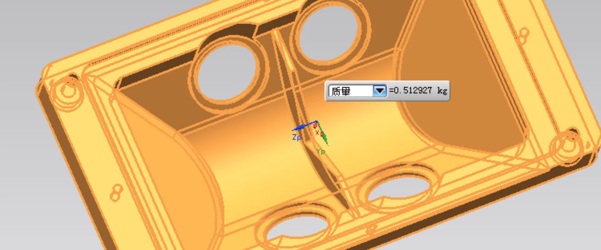
Defect Example Image
Reserve one clear defect photo, X-ray, CT scan, or sectioned sample that visually identifies the defect being discussed.
Best as a technical reference image
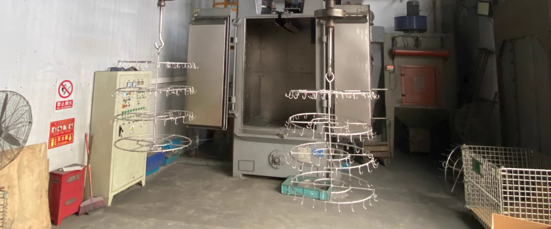
Corrective Action Image
Use a second image for tooling changes, gating adjustments, leak testing, or inspection steps that show how the defect is controlled.
Best as a process-improvement photo
Cold shut is one of the more insidious die casting defects because it is sometimes visible on the surface (a seam or line) and sometimes not (an unbonded interface visible only on cross-section or in pressure testing). Unlike porosity, which is distributed, cold shut occurs at specific locations in the casting geometry -locations predictable from the fill pattern.
What Cold Shut Is
Cold shut occurs when two separate metal flow fronts -flowing from different directions within the cavity -meet before either has fully solidified, but fail to achieve metallurgical bonding because the surfaces are too cool. The result is an interface within the casting where the two solidified metal regions are in contact but not bonded.
On the surface, this appears as a fine line, seam, or slight depression -often confused with a parting line mark but occurring mid-face rather than at a die interface.
How Cold Shut Forms
Metal fills a die cavity from one or more gates, flowing in multiple directions. Where two flow fronts meet:
If both fronts are still fully liquid: The fronts merge completely. No defect.
If one or both fronts have begun to solidify: The flow front surfaces have formed a thin oxide skin and partially solidified structure. When these partially solidified surfaces contact each other, the oxide skins prevent metallurgical fusion. The result is a seam -two pieces of metal in contact but not bonded.
Locations Where Cold Shut Occurs
Cold shut appears at predictable locations determined by fill geometry:
- End of flow: Where metal traveling the longest distance in the cavity finally stops and meets metal from another direction
- Thin sections between thick sections: Metal fills thick areas quickly, then has to fill thin connecting sections where it may have partially solidified
- T-junctions and U-turns in cavity geometry: Where flow direction reverses or divides and rejoins
- Around cores and inserts: Metal splits to flow around a core and must fuse on the downstream side
Identifying Cold Shut
Visual inspection: Fine seam or line on the casting surface, sometimes slightly indented or discolored. May be confused with parting line flash but occurs away from the parting line.
Dye penetrant inspection: Cold shuts open to the surface will retain penetrant, showing clearly as a red or fluorescent line under UV light.
Metallographic cross-section: Thin unbonded interface, often with associated oxide film. The interface may appear as a fine crack or gap.
Pressure testing: Cold shuts that penetrate through the casting wall create leak paths. A casting that passes visual inspection but fails pressure test often has a cold shut in a pressure-critical section.
X-ray: Cold shuts that create a significant gap show as a fine dark line on X-ray. Tight cold shuts may not be visible on X-ray.
Prevention -Design Approaches
Minimize flow length: The longer the flow path, the more metal cools before reaching the end. Gates positioned to achieve short, direct fill paths reduce cold shut risk. Mold flow simulation identifies fill lengths before tooling is cut.
Add overflow wells: Position overflows at locations where flow fronts meet. The overflow accepts the cold-front metal (which would create cold shut if left in the cavity), replacing it with fresh hot metal following behind.
Eliminate sharp-cornered re-entrant geometry: Features that cause metal to split, travel around, and rejoin are cold shut candidates. Radius the downstream side of cores and bosses.
Thin-section redesign: Thin connecting sections between thick sections cool fastest and are the most common cold shut locations. Thicken connecting sections or add flow channels (later machined away) to maintain metal temperature through them.
Prevention -Process Approaches
Increase injection velocity (fast shot): Faster fill means metal arrives at the far end of the cavity while still liquid. Higher gate velocity is the most direct remedy for fill-related cold shuts -but must be balanced against gas porosity risk from increased turbulence.
Increase metal temperature: Higher superheat keeps metal liquid longer during the fill time. Effective but increases die thermal load and reduces die life.
Increase die temperature: Higher die temperature reduces the rate of heat extraction from the metal during fill, maintaining fluidity longer. Effective but increases cycle time.
Cold Shut vs Flash -Not the Same
Cold shut (unbonded internal interface) and flash (thin metal fin at parting line or slide interface) are completely different defects with different causes and remedies. Cold shut is a structural defect; flash is a tooling/process defect. Both appear as surface irregularities, which causes confusion -but the location is diagnostic: flash occurs only at die component interfaces, cold shut can appear anywhere on the casting face.
Defect analysis and DFM: yaoqingpu1983@gmail.com | +86 138 1403 4409
Related Resources
Next steps for cold shut die casting
Misrun & Short Shot in Die Casting - Causes & Fixes
Misrun and short shot die casting defects: incomplete cavity fill, how to identify unfilled areas, root causes in thin sections and long flow paths, and process fixes for HPDC aluminum and zinc.
Defect GuideDie Casting Soldering & Blistering -Causes and Preve...
Soldering (die erosion) and blistering in die casting: why aluminum bonds to die steel, how blisters form during T6 heat treatment...
Quality GuideDie Casting Defects
Compare common defect types, causes, and corrective actions from a buyer and engineering perspective.
CapabilityQuality Control
Review inspection workflow, traceability support, and process control standards before launch.
Process GuideDie Casting Process
See how casting, trimming, machining, finishing, and inspection fit together in production.
Next StepRequest a Quote
Send your drawing package and target volume to get an engineering-backed quotation.
Need a Quote for Your Project?
Our engineering team is ready to review your requirements and provide competitive pricing with fast turnaround.
Request a Quote