Die Casting Wall Thickness - Minimum & Maximum
Practical die casting wall thickness guide for aluminum, zinc, and magnesium parts, including minimum walls, thick sections, ribs, and DFM rules.

Qingpu Yao
Process & Quality Engineering
Blog Visual Plan
Article visuals for die casting wall thickness
These visuals use your current KastMfg image library now, and they will automatically switch to article-specific images when you add them later.
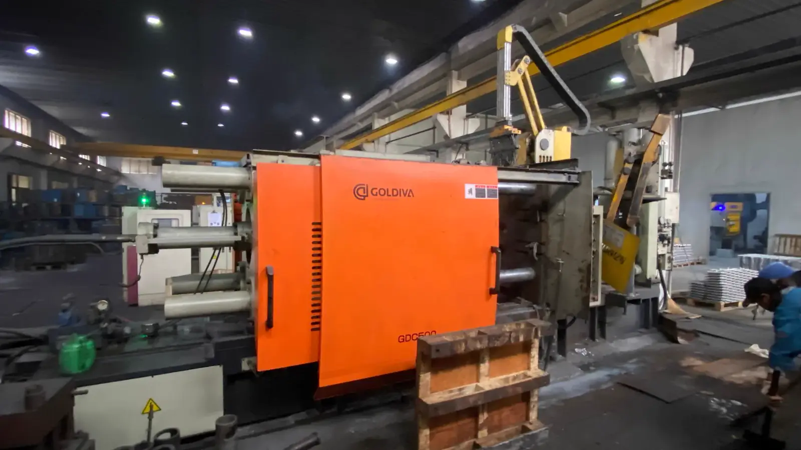
Lead Technical Image
Add a hero-level manufacturing, tooling, or component image that reinforces the article topic above the body copy.
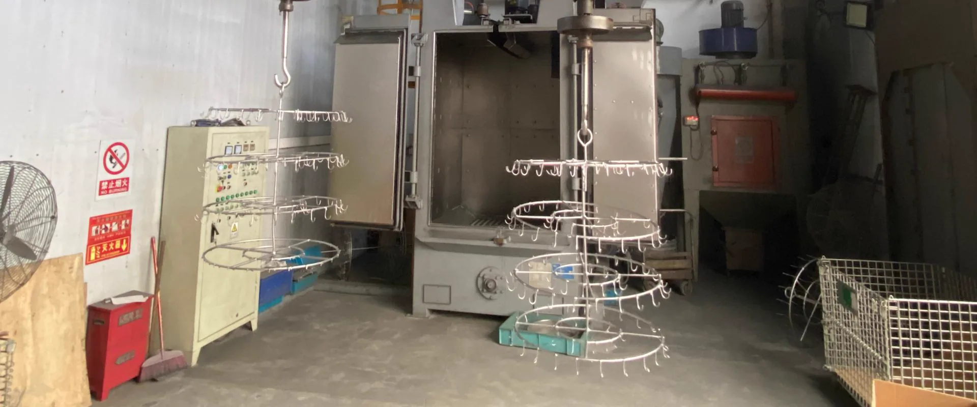
Comparison or Detail Image
Reserve a second image for an alloy comparison, defect example, tooling detail, or application close-up deeper in the article.
Die casting wall thickness controls metal flow, cooling rate, porosity risk, part strength, dimensional stability, cycle time, and scrap rate. Uniform wall thickness is one of the most important -and most frequently violated -design rules for aluminum, zinc, and magnesium die castings.
The goal is not to make every wall as thin as possible. The goal is to keep walls consistent, eliminate isolated heavy sections, and use ribs and coring instead of solid mass where stiffness or material is needed.
Recommended Wall Thickness by Alloy
| Alloy Family | Preferred Range | Practical Minimum | Heavy Section Risk Starts |
|---|---|---|---|
| Aluminum (A380, ADC12) | 2.0-4.0 mm | 1.2 mm | Above 6.0 mm |
| Zinc (Zamak 3, Zamak 5) | 0.8-3.0 mm | 0.4 mm | Above 4.5 mm |
| Magnesium (AZ91D, AM60B) | 1.5-3.5 mm | 0.8 mm | Above 5.0 mm |
These are engineering guidance ranges. Actual limits depend on part size, flow length from gate to end-of-fill, machine tonnage, gate and runner design, and quality requirements. Parts with long flow paths may need thicker walls than these minimums to achieve complete fill.
Flow Length and Wall Thickness Relationship
Wall thickness cannot be evaluated without knowing how far molten metal must travel. A 1.5 mm aluminum wall 30 mm from the gate is very different from the same wall 200 mm from the gate.
| Flow Length | Practical Minimum Wall (Aluminum) |
|---|---|
| Up to 50 mm | ~1.2-1.5 mm possible |
| 50-100 mm | ~1.5-2.0 mm |
| 100-200 mm | ~2.0-2.5 mm |
| Over 200 mm | ~2.5 mm or above depending on geometry |
Zinc fills thin sections more reliably than aluminum due to its lower melting point and faster injection in hot-chamber machines. Magnesium fills well but requires careful temperature and speed control for very thin walls.
Why Uniform Walls Matter
| Design Condition | Production Risk |
|---|---|
| Isolated thick boss on thin wall | Shrinkage porosity and visible sink marks on opposite surface |
| Abrupt thick-to-thin transition | Flow turbulence, cold shut, and stress concentration |
| Long thin wall far from gate | Incomplete fill or cold shut at end of flow path |
| Heavy rib root without core relief | Local porosity at junction |
| Thick cosmetic outer wall | Surface defects after finishing -flow marks, shrink, blistering during heat treatment |
| Non-uniform wall causing warpage | Dimensional non-conformance and assembly fit problems |
Non-uniform cooling is the root cause of most die casting dimensional and porosity problems. Heavy sections take longer to solidify, pulling material from adjacent thinner walls and creating shrinkage voids.
Rib Design Rules
Ribs are the correct solution when wall stiffness is needed without adding overall wall thickness. A rib provides structural efficiency by concentrating material where bending resistance is needed.
Key rib design rules:
| Parameter | Guideline |
|---|---|
| Rib thickness at base | 60-80% of the nominal wall the rib connects to |
| Rib height | Typically no more than 3-5x the rib base thickness |
| Draft on rib faces | Minimum 1-2 degrees per side (aluminum); 0.5-1 degree (zinc) |
| Radius at rib base | Minimum 0.5-1.0 mm -sharp corners cause stress and porosity |
| Rib spacing | Typically 3-5x the rib thickness to allow metal flow between ribs |
The 60-80% rib thickness rule exists because a rib thicker than 80% of the wall it connects to creates a heavy section at the junction. Heavy junctions cool slower than surrounding walls, forming shrinkage porosity exactly where the part needs to be solid and strong.
Cycle Time and Wall Thickness
Wall thickness directly affects cycle time because solidification time scales roughly with the square of the wall thickness.
| Wall Thickness | Approximate Solidification Time Ratio (aluminum) |
|---|---|
| 2 mm | 1x (reference) |
| 3 mm | ~2.25x |
| 4 mm | ~4x |
| 6 mm | ~9x |
Doubling wall thickness roughly quadruples the time required for solidification. Heavy sections in otherwise thin-walled parts extend the whole cycle to match the thickest section -increasing cost for every part, every cycle. Coring out heavy sections reduces cost and porosity simultaneously.
Thin Wall vs Thick Wall Trade-Off
| Choice | Benefit | Risk |
|---|---|---|
| Thin uniform walls | Lower weight, faster cooling, lower material cost | Fill problems if too thin for flow length |
| Thick walls | More machining stock, local strength | Porosity, sink marks, long cycle time, higher part cost |
| Ribs and pockets | Better stiffness-to-weight ratio | More complex tool design and draft requirement |
| Cored-out bosses | Reduces heavy sections without losing height | Core pin adds tooling complexity |
| Machined pads | Accurate functional surfaces after casting | Added CNC cost |
Good DFM combines moderate nominal walls, ribs, local pads, and controlled machining allowance -not a single heavy section where geometry allows it.
Design Rules Summary
- Define a consistent nominal wall and treat deviations as intentional exceptions.
- Keep rib thickness at 60-80% of the wall the rib reinforces.
- Core out thick bosses, pads, and isolated masses where possible.
- Add smooth radii at all wall transitions -no sharp steps.
- Avoid local thick sections more than 2x the nominal wall without adding coring.
- Review gate location when any thin wall is more than 150 mm from the injection point.
- Add machining allowance only where CNC operations are planned.
- Review wall uniformity in mold flow simulation before cutting steel.
For detailed guidance on radii, bosses, and slide design, see the die casting DFM guide.
Common Buyer Mistakes
| Mistake | Result |
|---|---|
| Adding thick wall sections "for strength" without DFM review | Porosity forms in the thick zone -part fails pressure or mechanical test |
| Specifying rib thickness equal to the wall it supports | Heavy junction at rib base creates shrinkage voids |
| Ignoring flow length when setting minimum wall | Incomplete fill or cold shut in thin far-from-gate walls |
| Adding machining allowance everywhere, not just on machined faces | Unnecessarily heavy sections and longer cycle time |
| Not coring out tall bosses | Shrinkage in boss center and surface sink on opposite side |
RFQ Checklist
Send the supplier:
- 3D model and 2D drawing with all nominal wall callouts
- Critical wall areas and any areas where minimum wall is needed for function
- Strength or load requirements for the structural sections
- Machined surfaces and required machining allowance
- Cosmetic surface requirements and acceptable defect level
- Leak testing or pressure testing requirements
- Annual volume and batch quantity
- Target alloy
KastMfg reviews wall thickness consistency, rib geometry, boss coring, and gate location during DFM before tooling release. Submit drawings through the RFQ page.
FAQ
What is the minimum wall thickness for aluminum die casting?
Aluminum die casting practical minimum is around 1.2 mm close to the gate. For walls more than 100 mm from the gate, 2.0 mm or more is typically needed for reliable fill. Final limits depend on alloy, machine, and gate design.
Can zinc die casting achieve thinner walls than aluminum?
Yes. Zinc hot-chamber die casting reliably fills walls down to 0.4-0.6 mm in small parts. Zinc's lower melting temperature and excellent fluidity make it the right alloy family for very thin, precise, small components.
How thick is too thick for die casting walls?
Sections above 6 mm in aluminum die casting create significant porosity risk. If a heavy section is required, core it out from the back. If coring is not possible, vacuum-assisted die casting or pressure-tight casting process controls should be reviewed.
What is the correct rib thickness for die casting?
Rib thickness at the base should be 60-80% of the wall it connects to. A rib thicker than 80% creates a heavy junction that forms shrinkage porosity. A rib thinner than 60% may be too fragile for ejection and production handling.
Does wall thickness affect part cost?
Yes, directly. Thicker walls use more material, cool more slowly, and extend cycle time. A 4 mm wall requires roughly 4x the solidification time of a 2 mm wall. Reducing unnecessary wall thickness in high-volume production can significantly reduce cost per part.
How does wall thickness affect porosity?
Heavy sections cool slower than adjacent thin walls, drawing molten metal from surrounding areas as they shrink. This creates internal porosity (invisible) and surface sinks (visible) in the thickest zones. Uniform wall thickness and proper coring are the primary prevention methods.
Can wall thickness be varied across a part?
Gradual transitions are acceptable. Abrupt steps from thin to thick walls create turbulence, cold shuts, and stress concentrations. Where wall thickness must change, add a tapered transition of at least 3-4x the wall thickness in length.
About The Author
Qingpu Yao on die casting wall thickness
Process & Quality Engineering
Focuses on DFM, tooling behavior, defect prevention, inspection planning, and production controls that affect yield and downstream machining stability.
Related Reading
Keep exploring the blog
DFM for Die Casting - Design Rules & Guidelines
A part optimized for die casting produces better quality at lower cost than a part designed without manufacturing in mind. DFM optimization reduces tooling complexity, lowers sc...
Qingpu Yao
6 min read
Die Casting Draft Angle - Rules & Exceptions
Draft angle in die casting is the taper applied to walls, ribs, bosses, holes, and textured surfaces so the solidified part can eject from the die without sticking, tearing, or...
Qingpu Yao
8 min read
Aluminum vs Zinc Die Casting - How to Choose
Aluminum and zinc are the two dominant die casting metals globally, together accounting for over 90% of all die casting volume by weight. Both produce complex, net-shape compone...
Qingpu Yao
5 min read
Magnesium Die Casting Applications & Key Uses
Magnesium die casting applications are strongest when lightweight structure, stiffness, thin-wall geometry, and premium feel matter. Magnesium alloys are commonly reviewed for e...
Qingpu Yao
3 min read