Die Casting DFM -Design for Manufacturability Rules
Complete DFM guide for die casting: draft angles, wall thickness, ribs, bosses, undercuts, radii, gate considerations, and tolerance guidelines....

Qingpu Yao
Process & Quality Engineering
Blog Visual Plan
Article visuals for DFM die casting
These visuals use your current KastMfg image library now, and they will automatically switch to article-specific images when you add them later.
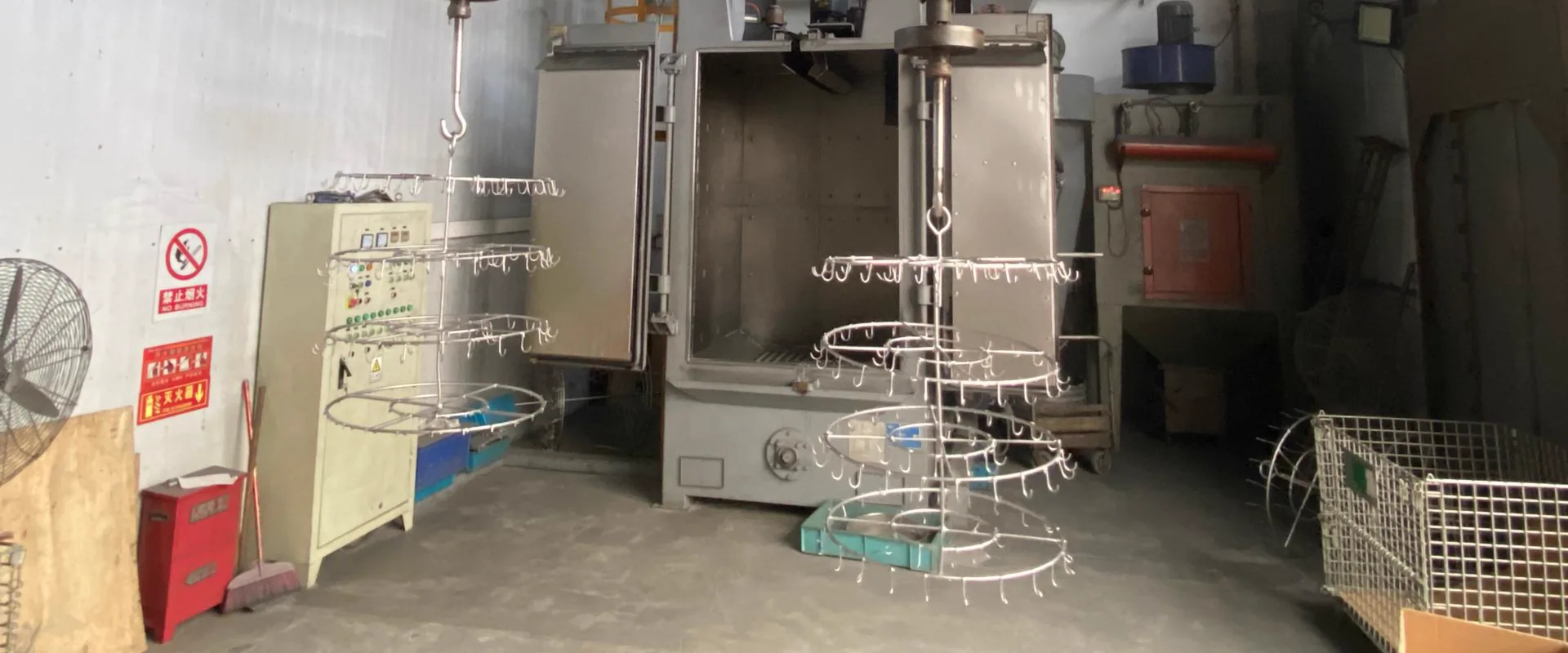
Lead Technical Image
Add a hero-level manufacturing, tooling, or component image that reinforces the article topic above the body copy.
Best as a wide industrial photo
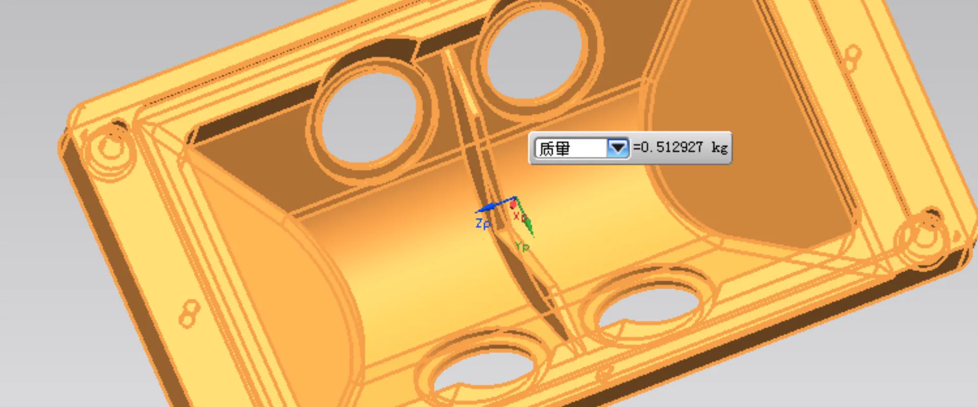
Comparison or Detail Image
Reserve a second image for an alloy comparison, defect example, tooling detail, or application close-up deeper in the article.
Best as a close-up or annotated visual
A part optimized for die casting produces better quality at lower cost than a part designed without manufacturing in mind. DFM optimization reduces tooling complexity, lowers scrap rates, extends die life, and achieves tighter tolerances without post-casting machining.
This guide covers every major DFM consideration for high-pressure die casting in aluminum, zinc, and magnesium -the same review process KastMfg's engineers perform on every customer drawing before quoting tooling.
1. Draft Angles
Draft angles -also called taper -are the slight angles applied to all surfaces parallel to the direction of die opening. Without sufficient draft, the casting cannot be ejected cleanly; the part binds on the die face and either tears or requires excessive ejector pin force that distorts the casting.
Recommended Draft Angles
| Feature | Aluminum | Zinc | Magnesium |
|---|---|---|---|
| External surfaces (cavity half) | 1-2° | 0.5-1° | 1-2° |
| Internal surfaces (core half) | 2-3° | 1-2° | 2-3° |
| Textured surfaces | Add 1-2° per 0.025 mm texture depth | Add 1-2° | Add 1-2° |
| Deep ribs (depth >5x width) | 3-5° | 2-3° | 3-5° |
| Blind holes (cores >3:1 depth/diameter) | 3-5° | 2-3° | 3-5° |
Rule of thumb: When in doubt, add more draft. Insufficient draft creates production problems every cycle; slightly more draft than minimum has no functional penalty in most applications.
2. Wall Thickness
Uniform wall thickness is the most important DFM principle in die casting. Thick sections cool more slowly than thin sections. Non-uniform cooling produces:
- Shrinkage porosity in thick sections
- Residual stress at thin-to-thick transitions
- Warpage as different sections contract at different rates
Recommended Wall Thickness by Alloy
| Alloy | Preferred Range | Absolute Minimum | Maximum Before Porosity Risk |
|---|---|---|---|
| Aluminum (A380) | 2.5-3.8 mm | 1.2 mm | 6 mm |
| Zinc (Zamak 3/5) | 1.5-2.8 mm | 0.4 mm | 5 mm |
| Magnesium (AZ91D) | 1.5-2.8 mm | 0.8 mm | 5 mm |
For sections exceeding the maximum: Use cored-out pockets to reduce local wall thickness. Reinforce with ribs rather than solid thick sections. A rib grid (1.5-2.8 mm ribs on 10 mm spacing) provides equivalent rigidity to a 5 mm solid wall with far less porosity risk.
Transitions Between Thick and Thin Walls
Abrupt thickness changes are as problematic as thick sections. Taper transitions gradually -a chamfer or fillet of at least 3:1 slope (3 mm run for every 1 mm step) between different wall thicknesses reduces flow disruption and shrinkage concentration.
3. Ribs
Ribs add stiffness and section modulus without adding bulk. Properly designed ribs prevent thick sections while maintaining structural performance.
Rib Design Rules
| Parameter | Rule |
|---|---|
| Rib thickness | 60-80% of the nominal wall it reinforces |
| Rib height | Maximum 5x rib thickness; use multiple shorter ribs for tall sections |
| Rib spacing | Minimum gap between ribs = 2x rib thickness |
| Root fillet | Minimum 0.4 mm; 1.0 mm preferred |
| Draft on rib faces | 2-3° per face (aluminum); 1-2° (zinc) |
Why the 60-80% rule? A rib thicker than 80% of the wall it connects creates a local thick section at the root -exactly the condition that causes shrinkage porosity. Thinner ribs cool faster, avoiding this.
4. Bosses
Bosses are cylindrical projections used for fastener holes, bearing locations, or assembly alignment. They are among the most common sources of die casting problems because they combine thick sections (the boss walls) with geometric complexity.
Boss Design Rules
| Parameter | Rule |
|---|---|
| Outer diameter | Minimum 2x inner bore diameter |
| Wall thickness | Same as general wall thickness rules (not thicker) |
| Root radius | Minimum 0.4 mm; 1.0 mm preferred |
| Stand-alone bosses | Connect to adjacent wall or neighboring boss with a rib |
| Draft on boss OD | 2-3° (aluminum); 1-2° (zinc) |
| Draft on bore | 2-3° (aluminum); 1-2° (zinc) |
Stand-alone bosses surrounded by thin metal are a common DFM failure. The boss cools slowly, the surrounding thin metal cools fast, and the differential creates a crack or shrinkage void at the boss root. Always connect bosses to the wall.
5. Undercuts and Slides
An undercut is any feature that prevents the casting from being pulled cleanly from the die in the main opening direction. Undercuts require side-pull slides, lifters, or collapsing cores -all of which add tooling cost and complexity.
Cost Impact of Slides
| Number of Slides | Approximate Tooling Cost Addition |
|---|---|
| 0 | Baseline |
| 1 slide | +$3,000-10,000 |
| 2 slides | +$8,000-20,000 |
| 3+ slides | +$15,000-40,000+ |
Design strategy: Before finalizing any feature that requires a slide, evaluate whether the undercut can be eliminated by:
- Rotating the parting line
- Replacing the undercut with a through-hole (accessible from the parting line)
- Redesigning the feature to pull in the main die direction
When undercuts cannot be eliminated, ensure the slide pull direction is at 90° or less to the parting line, and that slide travel is sufficient for complete disengagement.
6. Radii and Fillets
Internal Corners (Fillets)
All internal corners must have a fillet radius -never a sharp internal corner. Sharp corners:
- Create stress concentration in the casting at that location
- Create stress concentration in the die steel, accelerating thermal fatigue cracking
- Impede metal flow during injection, increasing porosity risk
| Condition | Minimum Fillet |
|---|---|
| General internal corners | 0.5 mm |
| Rib roots and boss roots | 1.0 mm preferred |
| Highly stressed areas | 2.0 mm or more |
External Corners
External corners (on the casting) can be sharp where required for function or assembly. A small chamfer (0.3-0.5 mm x 45°) reduces handling damage and deburring requirements without affecting function.
7. Holes and Cores
Through-holes in the die-opening direction are inexpensive -the core is part of the die. Specify through-holes rather than blind holes wherever possible.
Blind holes require a core that is more complex to cool and more prone to soldering. Aspect ratio (depth/diameter) should not exceed 3:1 for aluminum and 5:1 for zinc.
Holes perpendicular to die opening require slides -add cost. Evaluate whether these can be drilled by CNC machining after casting more economically than adding a slide to the die.
8. Tolerances
Die casting achieves CT4-CT6 tolerances (ISO 8062) as standard. Not all features require the same tolerance treatment:
| Feature Type | As-Cast Achievable | Post-Machining Required For |
|---|---|---|
| Linear dimensions | +/-0.1-0.5 mm (CT5) | +/-0.05 mm or tighter |
| Hole diameter | +/-0.1 mm | +/-0.02 mm (precision fits) |
| Hole position | +/-0.2-0.5 mm | +/-0.1 mm or tighter |
| Flatness | 0.1-0.3 mm | 0.02 mm (sealing faces) |
| Angularity | +/-0.5° | +/-0.1° |
Over-tolerancing is a common and expensive mistake. Specifying +/-0.05 mm on a non-critical dimension forces post-cast machining that costs more than the tolerance adds value. KastMfg's DFM review identifies over-toleranced features and recommends relaxation where functionally appropriate.
9. Parting Line Considerations
The parting line is where the die halves meet. It leaves a visible witness mark on the casting. Design considerations:
- Position parting lines on non-cosmetic surfaces where possible
- Parting lines on curved surfaces require more precise die machining -flat parting lines are lower cost
- Flash at the parting line is unavoidable; design so that flash occurs in areas that can be trimmed or ground without affecting function
- Tight tolerances across the parting line (features that span both die halves) require parting line alignment controls -add cost and complexity
KastMfg DFM Review
Every KastMfg quotation includes a free written DFM review covering all the areas above. If we identify castability concerns, we describe the specific feature, the problem it creates, and the recommended modification -with enough detail for your design team to evaluate the change.
Customers who engage with the DFM process before finalizing tooling commitment consistently achieve better first-trial results, lower tooling modification costs, and better production quality than customers who bypass it.
Request your free DFM review: yaoqingpu1983@gmail.com | +86 138 1403 4409 | No.6, Rungu Road, Nanjing, China
About The Author
Qingpu Yao on DFM die casting
Process & Quality Engineering
Focuses on DFM, tooling behavior, defect prevention, inspection planning, and production controls that affect yield and downstream machining stability.
Related Reading
Keep exploring the blog
Die Casting Wall Thickness - Minimum, Maximum & Desi...
Die casting wall thickness controls metal flow, cooling rate, porosity risk, part strength, dimensional stability, cycle time, and scrap rate. Uniform wall thickness is one of t...
Qingpu Yao
7 min read
Draft Angle in Die Casting - Rules, Exceptions & Too...
Draft angle in die casting is the taper applied to walls, ribs, bosses, holes, and textured surfaces so the solidified part can eject from the die without sticking, tearing, or...
Qingpu Yao
8 min read
Die Casting vs Gravity Casting -Process & Cost Compa...
High-pressure die casting and gravity casting both use metal molds, but they fill those molds in very different ways. High-pressure die casting injects molten metal into the die...
Qingpu Yao
3 min read
H13 vs P20 Die Casting Tooling Steel - When to Use Each
H13 and P20 are both tool steels, but they are not equal choices for die casting. H13 is the standard for production die casting cavities because it handles thermal fatigue, hea...
Qingpu Yao
6 min read