Aluminum Die Casting Heat Sinks: Design & Alloys
Guide to aluminum die casting heat sink design, alloys, fin geometry, machining, finishing, and quality checks for electronics and LED applications.

Qingpu Yao
Process & Quality Engineering
Blog Visual Plan
Article visuals for aluminum die casting heat sink
These visuals use your current KastMfg image library now, and they will automatically switch to article-specific images when you add them later.
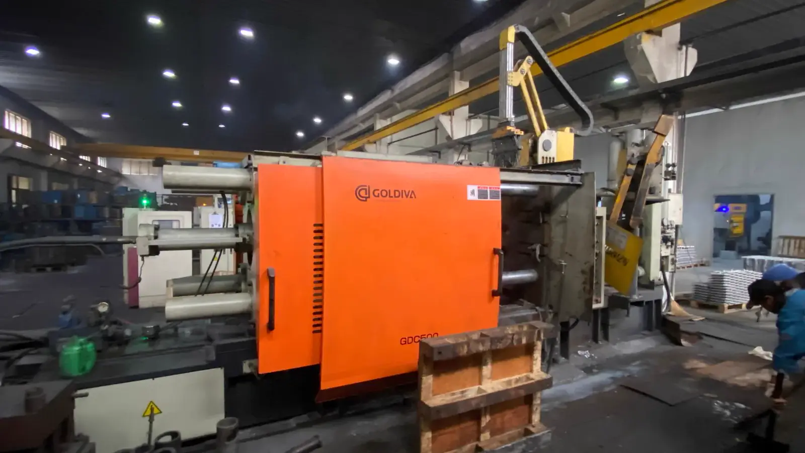
Lead Technical Image
Add a hero-level manufacturing, tooling, or component image that reinforces the article topic above the body copy.
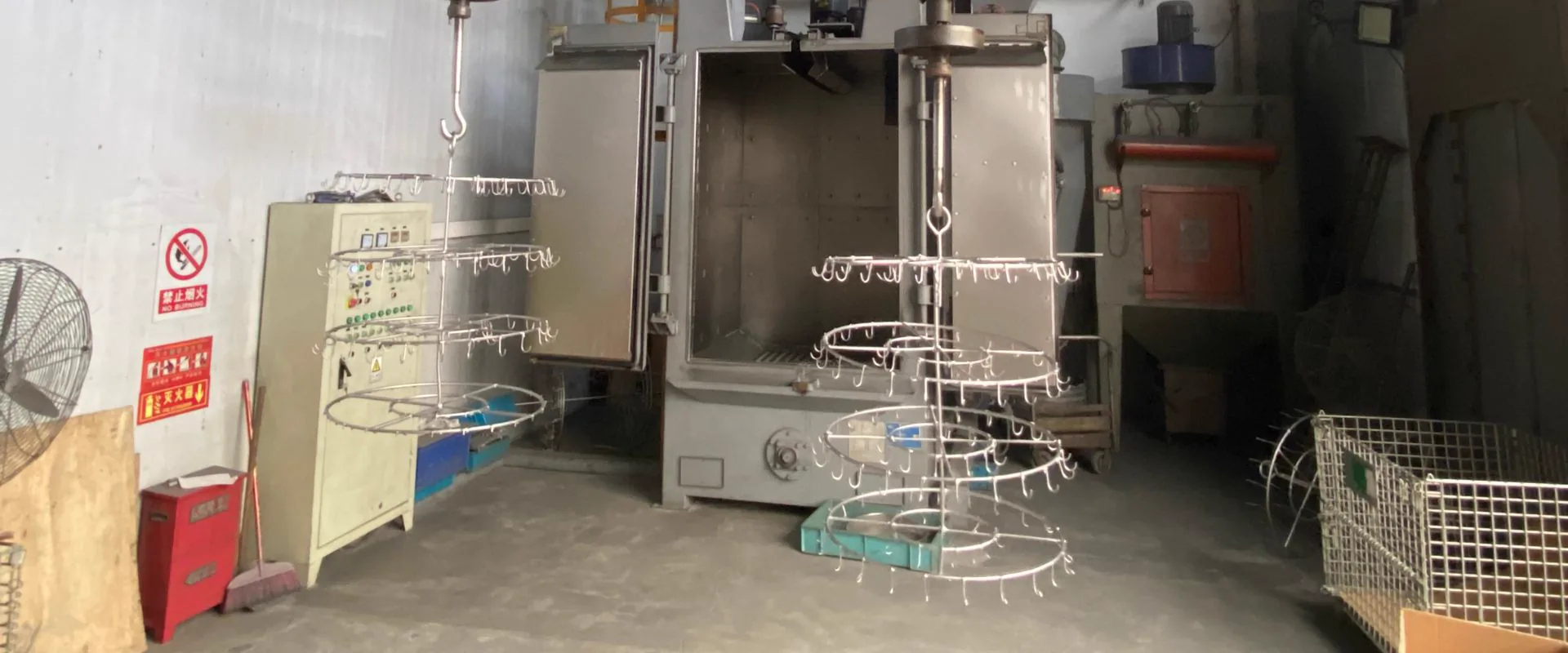
Comparison or Detail Image
Reserve a second image for an alloy comparison, defect example, tooling detail, or application close-up deeper in the article.
An aluminum die casting heat sink is a cast aluminum component that transfers heat away from electronics, LEDs, power modules, motors, or control units. Die casting is useful when the heat sink also needs mounting bosses, enclosure features, connector ports, sealing surfaces, or high-volume production consistency.
The key engineering question is not only "can this be cast?" It is whether the fin geometry, alloy thermal conductivity, surface finish, machining plan, and inspection method together deliver the required thermal performance in the production environment.
Where Die Cast Heat Sinks Fit Best
| Application | Why Die Casting Fits |
|---|---|
| LED lighting housings | Integrated fins, mounting bosses, sealing faces, and corrosion-resistant finishing in one part |
| Power electronics enclosures | Thermal paths, EMI shielding, connector features, and machined interfaces combined |
| Motor controller covers | Repeatable geometry with ribs, bosses, and gasket areas at volume |
| Telecom and outdoor equipment | Durable housing plus heat dissipation without secondary assembly |
| Industrial control boxes | Heat sink fins, enclosure walls, and mounting features combined |
| EV power modules | High-volume structural housings with integrated thermal management features |
Extruded aluminum profiles often provide better straight-fin thermal performance for simple geometries. Die casting becomes the right process when the heat sink needs three-dimensional features, integrated housing geometry, or complex mounting and sealing details that extrusion or machining cannot deliver economically.
Alloy Selection and Thermal Conductivity
Alloy choice directly affects how much heat the casting can transfer. The tradeoff is between thermal conductivity and castability -higher-silicon alloys fill thin features well but conduct heat less efficiently than lower-silicon alternatives.
| Alloy | Thermal Conductivity | Castability | Common Use |
|---|---|---|---|
| A380 | ~96 W/m·K | Excellent | General heat sink housings, motor covers, enclosures |
| ADC12 | ~96 W/m·K | Excellent | LED and electronics housings, similar to A380 |
| A360 | ~113 W/m·K | Good | Where higher conductivity justifies the process adjustment |
| A413 | ~121 W/m·K | Good for thin-wall fill | Pressure-tight housings with thermal requirements |
| Pure aluminum (wrought) | ~200 W/m·K | Not die-castable | Reference only -shows the gap from die cast alloys |
For most LED and electronics heat sink applications, A380 or ADC12 is the starting point. A360 is worth reviewing when thermal performance is a binding constraint and the design can accommodate its slightly lower fluidity. A413 is used when both heat transfer and leak-tightness matter, such as liquid-cooled power module housings.
Fin Geometry Rules for Die Casting
Fin geometry is where heat sink design most often conflicts with die casting process requirements. Very thin, tall, closely-spaced fins may look good in simulation but create fill, ejection, and tooling problems in production.
| Parameter | Practical Die Casting Range | Notes |
|---|---|---|
| Minimum fin thickness | 1.5-2.5 mm (aluminum) | Thinner fins increase fill and ejection risk |
| Maximum fin height | Typically up to 50-60 mm | Deeper fins require more draft and careful gate location |
| Fin height-to-thickness ratio | Typically 5:1 to 10:1 practical range | Higher ratios require careful process and tooling review |
| Fin draft angle | 1-2 degrees per side minimum | More draft needed on taller or textured fins |
| Fin spacing (pitch) | Typically 4-8 mm for die casting | Tighter spacing reduces fill and increases ejector risk |
| Fin-to-base junction radius | 0.5-1.0 mm minimum | Sharp base corners cause stress concentration and cracking |
Design rules for fins:
- Keep fin thickness consistent -avoid tapering that creates fill problems at the tip.
- Add draft so fins can eject cleanly without drag marks or tip breakage.
- Use radii at the fin base, not sharp corners.
- Orient fins parallel to the die pull direction wherever possible to avoid slides.
- Keep fin spacing wide enough for metal to fill completely.
- Place the gate so the last-fill area is not at a critical fin zone.
- Confirm airflow direction before finalizing fin layout -fins oriented against airflow reduce efficiency.
- Review with the supplier's mold flow simulation before cutting steel.
If the thermal target requires fin geometry beyond these ranges, vacuum-assisted die casting (VADC) or a hybrid design combining die cast housing with machined or extruded fin inserts may be the right solution.
Machining and Surface Finishing
Most heat sink castings need secondary operations:
| Operation | Purpose |
|---|---|
| CNC face milling | Flat thermal contact pad for device mounting |
| Drilling and tapping | Mounting holes for heat-generating components |
| Boring | Precise bores for press-fit inserts |
| Deburring | Remove flash and sharp edges from fins and edges |
| Powder coating | Corrosion and UV protection for outdoor housings |
| Conversion coating (chromate/alodine) | Thin electrical-compatible corrosion protection |
| Anodizing | Selected low-silicon alloys only -check alloy compatibility |
| Thermal interface masking | Protect contact pads from coating that would reduce heat transfer |
Critical design requirement: identify thermal contact surfaces on the drawing and specify whether they are coated or bare. A powder coat layer of 60-80 um on a device mounting pad can meaningfully increase thermal resistance. Masking adds cost but is necessary when contact surface conductivity matters.
Quality Checks for Heat Sink Projects
Request these documents at first article:
- DFM review confirmation before tooling release
- Material certificate (alloy and heat number)
- First article inspection report with all critical dimensions
- Flatness report on thermal contact pads (typically required to ±0.1-0.2 mm)
- Coating thickness report if powder coating is specified
- Thread gauge inspection for mounting holes
- Visual acceptance standard for fins, flow marks, and coating defects
- Packaging plan to protect fins from deformation during transit
For LED lighting projects, see the LED lighting die casting page and the LED streetlight housing case study.
Common Buyer Mistakes
| Mistake | Result |
|---|---|
| Designing fins too thin for aluminum die casting | Fill problems, fin breakage, or production instability |
| Coating the thermal contact pad without masking | Increased thermal resistance and device overheating |
| Using A380 when A360 conductivity is needed without checking | Thermal target not met in field testing |
| Specifying anodizing on A380 or ADC12 | Uneven or patchy anodize -these high-silicon alloys do not anodize well |
| Not specifying flatness on the thermal pad | Inconsistent contact resistance between units |
| Ignoring fin orientation relative to airflow direction | Designed thermal performance not achieved in real installation |
RFQ Information to Send
Send the supplier:
- 3D model and 2D drawing
- Thermal target or heat load if available (watts dissipated, maximum junction temperature)
- Required surface finish on all surfaces, with masking callouts
- Thermal contact pad flatness requirement
- Expected annual volume and batch size
- Any assembly mating parts (gaskets, screws, TIM pads, circuit boards)
- Outdoor exposure or IP rating requirement
- Packaging requirements to protect fins
The more precisely thermal and assembly requirements are defined at RFQ stage, the faster the supplier can assess whether die casting is the right process and whether the design is manufacturable.
FAQ
Is die casting good for aluminum heat sinks?
Die casting is good for aluminum heat sinks when the part needs integrated housing features, complex geometry, mounting bosses, or production volume above roughly 5,000 units per year. For simple straight-fin profiles in low volumes, machining from billet or extruded profile may be more economical.
Which aluminum alloy is best for die cast heat sinks?
ADC12 and A380 are the most common starting points -both offer good castability and approximately 96 W/m·K thermal conductivity. A360 provides around 113 W/m·K and is worth reviewing when heat dissipation is the binding design constraint. A413 offers higher conductivity but is primarily used when pressure tightness is also required.
What fin thickness is achievable in aluminum die casting?
Practical minimum fin thickness in aluminum die casting is typically 1.5-2.5 mm, depending on fin height, alloy, machine size, and gate location. Fins below 1.5 mm require very careful process design and may produce inconsistent fill in volume production.
Do coated heat sinks lose thermal performance?
A powder coat or paint layer on a thermal contact pad adds thermal resistance. For forced-air convection through fins, a coating on fin surfaces can actually improve emissivity and help radiation. The critical surface to keep bare or specify masking for is the direct device-mounting contact pad.
Can aluminum die cast heat sinks be anodized?
Standard die casting alloys A380 and ADC12 have high silicon content (7-12%) that causes uneven, patchy anodizing. A360 and A413 anodize more predictably. If anodizing is required for the application, alloy selection should be confirmed with the finisher before tooling release.
What flatness is achievable on a die cast thermal contact pad?
As-cast flatness on die cast surfaces is typically 0.2-0.5 mm over a 100 mm span. CNC face milling can achieve 0.05-0.1 mm flatness. For precision contact requirements, machining the pad after casting is the standard approach.
How should fins be protected during shipping?
Die cast fins are vulnerable to bending during transit. Packaging typically uses custom foam inserts, corner protectors, or individual bagging to prevent contact between fins and packaging material. The packaging plan should be reviewed before production shipment.
About The Author
Qingpu Yao on aluminum die casting heat sink
Process & Quality Engineering
Focuses on DFM, tooling behavior, defect prevention, inspection planning, and production controls that affect yield and downstream machining stability.
Related Reading
Keep exploring the blog
Aluminum Die Casting Electronics Enclosures Guide
Aluminum die casting for electronics enclosures is used when a housing needs mechanical protection, EMI shielding, heat dissipation, gasket sealing, connector features, and repe...
Qingpu Yao
4 min read
Magnesium Die Casting Applications & Key Uses
Magnesium die casting applications are strongest when lightweight structure, stiffness, thin-wall geometry, and premium feel matter. Magnesium alloys are commonly reviewed for e...
Qingpu Yao
3 min read
Aluminum Die Casting for Automotive: IATF & PPAP
Aluminum die casting is one of the primary manufacturing processes for automotive components because it combines lightweight structure, dimensional repeatability, thermal manage...
Qingpu Yao
8 min read
Zinc Die Casting Applications: Where Zamak Wins
Zinc die casting applications are strongest when parts need thin walls, tight detail, smooth surface finish, high dimensional repeatability, and efficient production of small to...
Qingpu Yao
3 min read