Die Casting Porosity Testing - X-Ray, CT & Leak
Guide to die casting porosity testing methods: X-ray, CT scan, leak testing, pressure testing, and vacuum impregnation, with acceptance criteria.

Qingpu Yao
Process & Quality Engineering
Blog Visual Plan
Article visuals for die casting porosity testing
These visuals use your current KastMfg image library now, and they will automatically switch to article-specific images when you add them later.
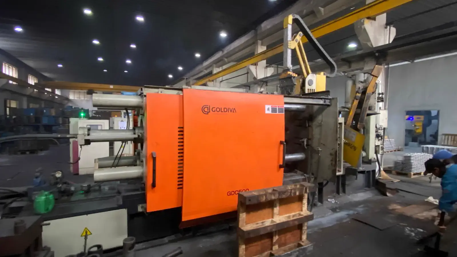
Lead Technical Image
Add a hero-level manufacturing, tooling, or component image that reinforces the article topic above the body copy.
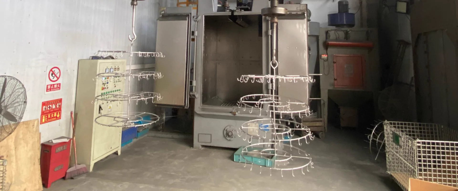
Comparison or Detail Image
Reserve a second image for an alloy comparison, defect example, tooling detail, or application close-up deeper in the article.
Die casting porosity testing checks whether internal voids, gas pores, shrinkage cavities, or connected porosity will affect strength, machining, sealing, pressure tightness, or surface appearance. The right test depends on the failure risk the porosity creates -not on whether any porosity exists.
Small isolated pores in non-critical zones are normal in HPDC and are generally acceptable. Porosity becomes a problem when it is located near machined sealing faces, pressure walls, threaded holes, fatigue-critical zones, or cosmetic surfaces that will be polished or plated.
Porosity Testing Methods
| Method | Best For | Typical Parameters | Limitation |
|---|---|---|---|
| X-ray (radiography) | Internal voids and shrinkage in selected zones | 80-300 kV source; film or digital flat-panel detector | 2D image only; overlapping features can obscure pores |
| CT scan (computed tomography) | 3D porosity mapping, failure analysis, first-article validation | 50-500 um voxel resolution; 20-400 kV depending on part size | Higher cost and longer scan time; large parts need industrial CT |
| Air decay leak test | Pressure-tight housings, fluid circuits | 0.1-3 bar test pressure; 10-60 second hold; pressure drop monitored | Finds connected leak paths -not isolated internal pores |
| Hydraulic pressure test | Functional burst and sealing test | 5-350 bar depending on application | Requires fixturing; destructive if burst tested to failure |
| Sectioning (metallurgical) | Process study, failure root cause, CT verification | Cross-section cut and polish; optical microscope | Destructive -typically done on samples, not production parts |
| Dye penetrant (PT) | Surface-connected cracks and defects | Applied to machined or polished surfaces | Only detects defects open to the surface |
| Vacuum impregnation | Sealing connected porosity before pressure testing | Sealant drawn into leak paths under vacuum, then cured | Corrective process -does not fix structural defects |
X-Ray Inspection in Practice
Industrial X-ray inspection of aluminum die castings typically uses:
- Source voltage: 100-200 kV for aluminum walls up to 50 mm thick; up to 300 kV for larger sections
- Digital flat-panel detectors (DR) are now standard for production inspection, replacing film in most facilities
- Reference standard: ASTM E505 reference radiographs for aluminum die castings define porosity grades 1-8 for gas porosity and shrinkage; automotive programs often specify maximum grade level per zone
- Coverage: X-ray images are taken from defined angles to cover critical zones; full volumetric coverage requires multiple projections
Buyers should specify which zones require X-ray coverage, the maximum allowable porosity grade per zone, and the projection angles needed to inspect those areas. A blanket "X-ray inspection required" note is not actionable without this detail.
CT Scan -When It Is Worth the Cost
Industrial CT scanning creates a full 3D volumetric image of the casting interior. It is more expensive and slower than X-ray, but it eliminates the ambiguity of overlapping features in 2D radiography.
CT is most useful for:
- First-article DFM validation -confirming gate fill, shrinkage location, and porosity distribution before production commit
- Failure analysis -identifying leak path geometry or fracture origin
- Complex internal geometries -passages, cooling channels, and walls where X-ray angles cannot isolate the critical zone
- Customer qualification -some automotive OEMs require CT on new die casting tools at PPAP
Practical parameters for aluminum die casting CT:
- Voxel resolution: 50-200 um typical for production-size parts
- Part size limit: benchtop CT systems typically handle parts up to 300-400 mm; large industrial systems handle larger parts at reduced resolution
- Scan time: 10-60 minutes per part depending on resolution and size
CT is generally not cost-effective for 100% production inspection. It is best used at first article, during process troubleshooting, and for periodic audit samples.
Leak Testing -Parameters That Matter
A leak test confirms whether a casting is pressure-tight to the functional specification. It does not reveal internal porosity that is not connected to the surface.
Key parameters buyers must define:
| Parameter | Typical Range | Notes |
|---|---|---|
| Test medium | Air, nitrogen, or helium | Air/nitrogen for most parts; helium for very low leak rates |
| Test pressure | 0.1-3 bar for general housings; 5-350 bar for hydraulic parts | Must match functional working pressure with appropriate safety factor |
| Hold time | 10-120 seconds | Longer hold detects slower leaks |
| Acceptance criterion | Maximum pressure drop (e.g., <0.05 bar in 30 seconds) or maximum flow rate | Must be defined numerically on the drawing or control plan |
| Fixture design | Critical for repeatable sealing of test ports | Poorly designed fixtures cause false rejects |
For hydraulic manifolds and high-pressure parts, test pressure is typically 1.5x working pressure. For general housings with gasket seals, lower test pressures (0.1-0.5 bar) are common.
Ambiguous leak test notes such as "no leaks allowed" or "must be airtight" are not inspectable. The drawing must specify pressure, medium, hold time, and acceptance criterion.
When Each Test Is Needed
| Part Type | Recommended Tests |
|---|---|
| Hydraulic manifold (operating >100 bar) | Pressure test + leak test; X-ray or CT for porosity near bores |
| EV motor housing with water cooling | Leak test at 0.1-0.3 bar; CMM after machining; X-ray if OEM requires |
| LED lighting housing | Visual and dimensional inspection; no leak test typically required |
| Decorative plated zinc part | Surface and visual inspection before plating; no structural testing |
| Automotive structural bracket | Critical-zone X-ray if load-bearing; CMM on all datums |
| General equipment cover | Visual and dimensional inspection only |
| Pump body (operating <10 bar) | Leak test; optional X-ray on port and thread zones |
Do not apply automotive-level testing to general industrial parts. Testing cost should be proportional to the failure consequence.
Acceptance Criteria -How to Write Them
Buyers should define porosity requirements clearly on the drawing or in a separate specification:
- Zone map: Identify critical zones (sealing faces, pressure walls, thread areas, fatigue zones) and non-critical zones separately
- Porosity grade: Specify maximum ASTM E505 grade (or equivalent) per zone -for example, Grade 3 maximum in non-critical zones, Grade 1 maximum within 5 mm of a machined sealing face
- Leak test spec: Pressure, medium, hold time, and maximum acceptable pressure drop or flow rate
- Sampling plan: 100% inspection, AQL sampling (e.g., AQL 0.65 for critical, AQL 2.5 for major), or periodic audit
- Impregnation: Explicitly state whether vacuum impregnation is permitted, prohibited, or requires customer approval
Vague notes like "no porosity allowed" are unenforceable and guarantee disagreements at first article.
Vacuum Impregnation
Vacuum impregnation is a repair process that seals connected porosity in leak-sensitive castings. The casting is placed in a vacuum chamber, resin sealant is introduced, and vacuum then pressure cycle drives the sealant into connected pores. The sealant is cured at low temperature.
| Use Impregnation When | Avoid Relying on It When |
|---|---|
| Minor connected porosity causes leakage in otherwise stable production | Porosity is large, structural, or near a high-stress zone |
| Customer drawing permits or approves the process | Drawing explicitly prohibits sealing processes |
| Part passes leak test after impregnation | Root cause is unstable gating, venting, or die temperature |
| Aerospace and medical parts rarely permit impregnation | These industries typically require porosity-free castings by process control |
Impregnation can be a legitimate process tool for automotive fluid parts when the customer approves it. It should not be used to mask systemic process problems.
RFQ Checklist
Send the supplier:
- Drawing with critical zones identified
- Leak or pressure test specification (pressure, medium, hold time, acceptance criterion)
- X-ray or CT requirement with porosity grade limits per zone
- Machined sealing surface locations and flatness requirements
- Annual volume and inspection sampling plan
- Whether impregnation is permitted, prohibited, or requires written approval
- Required inspection documents and traceability records
KastMfg reviews porosity risk during DFM and can recommend gating, venting, vacuum assist, and testing methods before tooling is released. Submit drawings through the RFQ page.
FAQ
What is the best test for die casting porosity?
There is no single best test. X-ray reveals internal voids in 2D; CT provides full 3D mapping; leak testing confirms pressure tightness; sectioning confirms metallurgical structure. The right test depends on the failure mode the customer is trying to prevent.
What X-ray standard is used for aluminum die casting porosity?
ASTM E505 is the most widely used reference radiograph standard for aluminum alloy castings. It defines porosity grades 1-8 for gas porosity and shrinkage. Automotive OEMs often specify a maximum grade level per drawing zone.
Does every die casting need X-ray inspection?
No. X-ray is appropriate for pressure-critical zones, structural load-bearing areas, and OEM-required inspections. General covers, brackets, and enclosures typically do not require X-ray unless specified.
What leak test pressure is typical for die casting?
Common ranges are 0.1-0.5 bar for general housing sealing and 5-350 bar for hydraulic or high-pressure applications. Test pressure should be defined relative to the functional working pressure with a safety factor. The exact pressure, medium, hold time, and acceptance criterion must be written on the drawing.
Can impregnation fix structural porosity?
No. Vacuum impregnation seals connected leak paths with resin sealant. It improves pressure tightness but does not improve mechanical strength. Large voids, cracks, and cold shuts require process correction, not impregnation.
How is CT scan resolution described?
CT scan resolution for die casting is typically described as voxel size -the smallest feature that can be distinguished in the 3D volume. Typical values for aluminum die casting inspection are 50-200 um. Smaller voxel size requires longer scan time and limits the maximum part size that can be scanned.
What sampling plan should I specify for leak testing?
Common automotive practice is 100% production leak testing for fluid-critical parts such as hydraulic manifolds, cooling jackets, and pump bodies. For less critical housings, AQL-based sampling (e.g., AQL 0.65 or 1.0 for major characteristics) is typical. The sampling plan should be agreed during PPAP or in the control plan, not left open.
About The Author
Qingpu Yao on die casting porosity testing
Process & Quality Engineering
Focuses on DFM, tooling behavior, defect prevention, inspection planning, and production controls that affect yield and downstream machining stability.
Related Reading
Keep exploring the blog
Die Casting vs Gravity Casting - Process & Cost
High-pressure die casting and gravity casting both use metal molds, but they fill those molds in very different ways. High-pressure die casting injects molten metal into the die...
Qingpu Yao
3 min read
Die Casting Defects -Causes, Types & Solutions
The eight most common high-pressure die casting (HPDC) defects are gas porosity, shrinkage porosity, cold shut, flash, misrun, soldering, warpage, and blister. Each defect has d...
Qingpu Yao
6 min read
How to Choose a Die Casting Supplier - 8 Criteria
Evaluate die casting suppliers on eight criteria: process capability match, quality certifications, tooling capability and ownership policy, inspection and measurement capabilit...
Qingpu Yao
4 min read
Die Casting Tooling Steel: H13 vs P20 Compared
H13 and P20 are both tool steels, but they are not equal choices for die casting. H13 is the standard for production die casting cavities because it handles thermal fatigue, hea...
Qingpu Yao
6 min read