Leak Testing Die Castings -Air Decay, Helium & Press...
Complete guide to die casting leak testing: air decay, nitrogen, helium mass spectrometer, sensitivity comparison, test parameter specification...
Supporting Visuals
Supporting visuals for die casting leak testing
These images are pulled from your current KastMfg asset library. Page-specific files automatically override shared fallback visuals when you add them later.
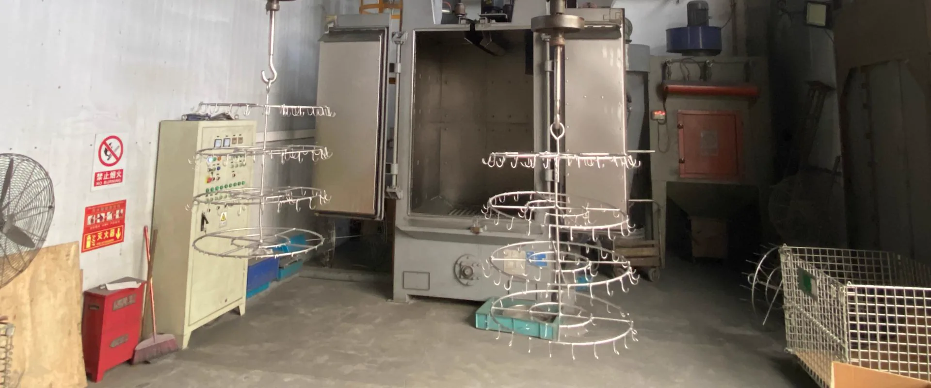
Factory or Process Image
Reserve space for a production, tooling, or inspection photo that visually supports the main topic.
Best as a wide industrial image
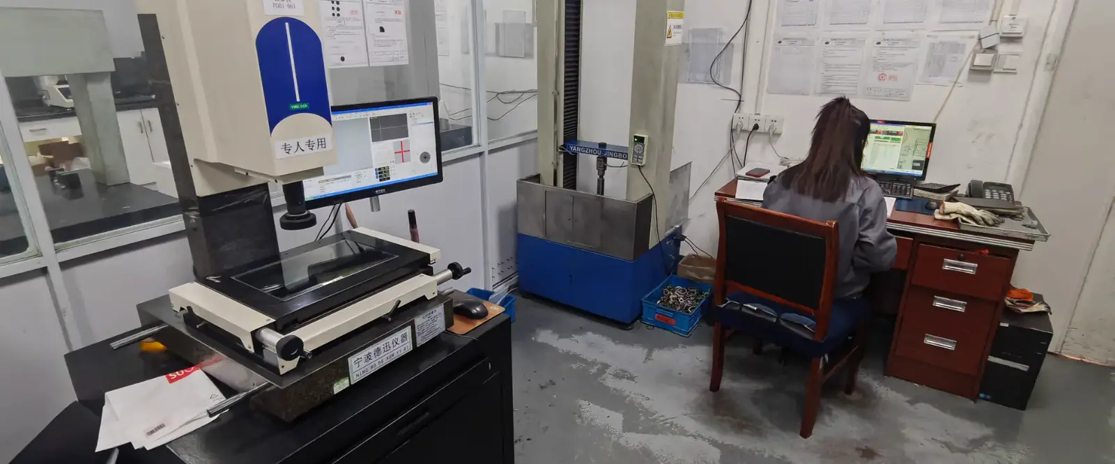
Component Detail Image
Use a close-up of a casting, surface finish, machined feature, or application component to add visual proof.
Best as a detail or macro shot
Leak testing is production verification, not quality inspection. It does not improve part quality -it separates conforming parts (which will seal in service) from non-conforming parts (which will not) before they reach the customer.
Methods Compared
| Method | Medium | Sensitivity | Speed | Cost | Best Application |
|---|---|---|---|---|---|
| Air decay | Dry compressed air | ~1 cm3/min | Fast (15-20 s) | Low | General pneumatic, low-pressure hydraulic |
| Nitrogen decay | Dry nitrogen | ~1 cm3/min | Fast | Low | Hydraulic (cleanliness), coolant circuits |
| Hydrostatic | Water | Visible leak | Moderate | Low | Burst pressure qualification |
| Helium tracer (hood) | Helium | <10^-8 mbar·L/s | Moderate | High | Refrigerant, sealed electronics, precision |
| Hydrogen tracer | H2/N2 mix | ~10^-7 mbar·L/s | Moderate | Medium | Alternative to helium |
Air Decay -Production Standard
Air decay is the standard 100% production test for hydraulic and pneumatic die cast components. The part is pressurized to the test pressure, valved off, and monitored for pressure decay.
Test sequence:
- Part clamped in fixture with test ports sealed
- Pressurize to test pressure (typically 1.25-2.5x rated working pressure)
- Valve off and allow 3- s stabilization (thermal equilibration)
- Monitor pressure decay for hold time (15-20 s)
- Compare actual decay to limit -pass or fail
Key sensitivities:
- Temperature variation of +/-1°C changes air pressure by ~0.3% -temperature-stabilized test rooms or temperature compensation essential for tight limits
- Part volume affects sensitivity -smaller part volume = more pressure drop for same leak rate = easier to detect small leaks
Typical acceptance criteria:
| Application | Test Pressure | Hold Time | Decay Limit |
|---|---|---|---|
| Pneumatic valve body (10 bar) | 15 bar | 30 s | <0.5 cm3/min |
| Hydraulic manifold (100 bar) | 150 bar | 45 s | <2 cm3/min |
| Cooling circuit (5 bar) | 8 bar | 30 s | <0.3 cm3/min |
Helium Mass Spectrometer Testing
Helium testing detects leak rates orders of magnitude smaller than air decay -down to 10^-8-10^-10 mbar·L/s. This sensitivity is necessary when:
- The fluid being sealed is expensive (refrigerant)
- Leakage creates regulatory or safety problems (oxygen systems, toxic gas)
- Service life requires leak-free integrity over years (hermetically sealed electronics)
- Standard air decay passes but field failures occur -indicating very small leak rates just below air decay detection
Hood (bomb) method: Part is pressurized internally with helium, placed inside a sealed chamber connected to the spectrometer. Accumulated helium concentration in the hood is measured after a dwell time. Best for production 100% testing of small to medium parts.
Sniffer probe method: Part is pressurized with helium; a probe is passed over external surfaces. Localizes the leak position. Best for qualification, troubleshooting, and root cause investigation.
How to Write a Pressure Test Specification
Vague specifications ("pressure tight," "no leaks") create supplier-customer disagreement. State the test method, medium, pressure, hold time, and acceptance criterion explicitly:
Good examples:
"100% air decay test. Test pressure: 150 bar. Stabilization: 5 s. Hold time: 45 s. Maximum decay: 2 cm3/min."
"100% helium leak test (hood method). Test pressure: 8 bar helium. Dwell time: 60 s. Maximum leak rate: 10^-6 mbar·L/s."
Common specification errors:
- Specifying "1.5x working pressure" without stating the working pressure
- Specifying decay rate without specifying part volume or test pressure
- Specifying "helium leak test" without specifying sensitivity limit or test method
KastMfg Pressure Testing Capability
| Equipment | Range | Sensitivity |
|---|---|---|
| Air decay test stations (4 units) | Up to 200 bar | <0.1 cm3/min |
| Nitrogen high-pressure station | Up to 350 bar | Pressure decay |
| Helium mass spectrometer (hood) | Any pressure | <10^-8 mbar·L/s |
All test records archived: part serial number, test date, test pressure, hold time, actual decay or leak rate, pass/fail. Available to customers on request for 5 years minimum.
Relationship Between Alloy, VADC, and Test Performance
| Alloy + Process | Typical Air Decay (100 bar, A size part) | Helium Leak Rate |
|---|---|---|
| A380 standard HPDC | 70-75% pass rate | 10^-4-10^-5 mbar·L/s typical |
| A413 standard HPDC | 90-97% pass rate | 10^-4-10^-5 mbar·L/s |
| A413 + VADC | 99-100% pass rate | <10^-6 mbar·L/s |
| A380 + VADC | 98-100% pass rate | <10^-6 mbar·L/s |
Pressure test specification support: yaoqingpu1983@gmail.com | +86 138 1403 4409
Related Resources
Next steps for die casting leak testing
Types of Die Casting -HPDC, LPDC, Gravity, Hot & Col...
Complete overview of all die casting types: high pressure, low pressure, gravity, hot chamber, cold chamber, vacuum...
Process GuideGravity Die Casting -Process, Advantages & Compariso...
What is gravity die casting (permanent mold casting)? Learn how it differs from high pressure die casting, when to choose it, typical alloys...
ToolingDie Casting Tooling
Connect process decisions back to gate design, thermal balance, and die maintenance planning.
CapabilityQuality Control
Review inspection workflow, traceability support, and process control standards before launch.
Process GuideDie Casting Process
See how casting, trimming, machining, finishing, and inspection fit together in production.
Next StepRequest a Quote
Send your drawing package and target volume to get an engineering-backed quotation.
Need a Quote for Your Project?
Our engineering team is ready to review your requirements and provide competitive pricing with fast turnaround.
Request a Quote